Current Electricity
15 previous year questions.
High-Yield Trend
Chapter Questions 15 MCQs
Official Solution
While electric current ( ) is a scalar quantity that tells us the total amount of charge flowing through a cross-section of a conductor per unit time, it doesn't describe how the flow is distributed across that cross-section. Current density ( ) provides this microscopic description. It is a vector pointing in the direction of the flow of positive charge.
Step 2: Key Formula and Discussion:
Magnitude:
If a current flows uniformly through a conductor with a cross-sectional area perpendicular to the flow, the magnitude of the current density is:
Vector Nature:
Current density is a vector, . The total current through a surface is the flux of the current density vector through that surface:
This integral form is more general and accounts for non-uniform current distribution and surfaces that are not perpendicular to the current flow.
Relation to Drift Velocity:
Current density is related to the microscopic properties of the charge carriers. If a conductor has charge carriers per unit volume, each with charge and moving with an average drift velocity , the current density is given by:
For electrons, , so . Since the conventional current direction is opposite to the electron drift velocity, is in the direction of conventional current.
Relation to Ohm's Law (Microscopic Form):
Current density is directly related to the electric field ( ) within the conductor. This relationship is the microscopic or point form of Ohm's Law:
where is the electrical conductivity of the material ( , where is the resistivity). This equation states that the current density at a point is directly proportional to the electric field at that point.
Step 3: Final Answer:
Current density is the vector measure of electric current flow per unit area at a point. It is fundamental in relating macroscopic quantities like current to microscopic quantities like drift velocity and the local electric field.
Official Solution
An ammeter is a device used to measure current in a circuit and is always connected in series. A "shunted ammeter" refers to an ammeter (or more accurately, a galvanometer) that has a low-resistance resistor, called a shunt, connected in parallel with it. This is done to extend the range of the ammeter. The question asks what effect this has on the total resistance of the circuit.
Step 2: Key Formula or Approach:
When resistors are connected in parallel, the equivalent resistance ( ) is always less than the smallest individual resistance. The formula for two resistors in parallel is:
Here, is the ammeter's internal resistance ( ), and is the shunt resistance ( ). The effective resistance of the shunted ammeter is .
Step 3: Detailed Explanation:
1. An ammeter is placed in series in a circuit. Let the original total resistance of the circuit be , where is the ammeter's resistance and is the resistance of the rest of the circuit.
2. When the ammeter is shunted, a low-resistance shunt ( ) is connected in parallel to the ammeter's internal resistance ( ).
3. The new effective resistance of the measuring instrument, , is the parallel combination of and .
4. Since the equivalent resistance of a parallel combination is always smaller than the smallest of the individual resistances, and a shunt has very low resistance, we have . And since is chosen to be much smaller than , it is certain that .
5. The new total resistance of the circuit becomes .
6. Since , it follows that .
Therefore, shunting an ammeter decreases its own effective resistance, which in turn decreases the total resistance of the circuit it is part of.
Step 4: Final Answer:
If an ammeter is shunted, the total resistance of the circuit decreases. Option (B) is correct.
Official Solution
Drift velocity is the average velocity attained by charged particles, such as electrons, in a material due to an electric field. In a conductor, free electrons move randomly. When an electric field is applied, they experience a force that superimposes a small, directional 'drift' on their random motion.
Step 2: Key Formula or Approach:
The electric field exerts a force on each free electron (charge ).
This force causes an acceleration , where is the mass of the electron.
Between collisions with the lattice ions, the electron accelerates. The average time between collisions is called the relaxation time ( ).
The drift velocity is the average velocity gained during this time, given by .
Step 3: Detailed Explanation:
Substituting the expression for acceleration into the drift velocity equation: For a given conductor at a constant temperature, the charge , mass , and relaxation time are all constants.
Therefore, the drift velocity is directly proportional to the applied electric field . Step 4: Final Answer:
The drift velocity is directly proportional to the applied electric field. Therefore, option (A) is correct. This relationship is also the microscopic basis for Ohm's law.
Official Solution
A potentiometer is a device used for accurately measuring an unknown electromotive force (e.m.f.) or potential difference by balancing it against a known potential difference.
It operates on the principle of null deflection, meaning it draws no current from the circuit being measured at the point of balance.
Step 2: Detailed Explanation:
The working principle of a potentiometer is that the potential drop across any portion of a wire of uniform cross-section and composition, carrying a constant current, is directly proportional to its length.
When we measure the potential difference of a cell using a potentiometer, we find a "null point" on the potentiometer wire where the galvanometer shows zero deflection.
At this null point, the potential difference of the cell is exactly equal to the potential drop across that length of the potentiometer wire.
Since no current is drawn from the cell at this point, the measurement is of the true e.m.f. or potential difference, making it more accurate than a standard voltmeter.
While it can be adapted to measure current and resistance indirectly, its primary and main function is the precise measurement of potential difference.
Step 3: Final Answer:
Based on its principle and primary application, a potentiometer is mainly used to measure potential difference. Therefore, option (C) is the correct answer.
Official Solution
When current flows through a resistor, electrical energy is converted into thermal energy. This is known as Joule heating.
Step 2: Key Formula or Approach:
The thermal energy ( ) developed in a resistor is given by Joule's law of heating:
where is the current, is the resistance, and is the time for which the current flows.
Step 3: Detailed Explanation:
The two resistors, and , are connected in series.
In a series circuit, the current flowing through each component is the same. Let this current be .
The time for which the current flows is also the same for both resistors.
Therefore, the thermal energy developed in each resistor is directly proportional to its resistance ( ).
Let be the energy developed in resistor and be the energy developed in resistor .
To find the ratio of the thermal energy, we divide by :
The terms and cancel out, leaving:
So, the ratio of the thermal energy is .
Step 4: Final Answer:
The ratio of thermal energy developed in R and 2R is 1:2. Therefore, option (A) is correct.
Official Solution
This question asks to describe the overall motion of a free electron inside a conductor when an electric field is applied (i.e., when a current is flowing).
Step 2: Detailed Explanation:
Free electrons in a conductor are in a state of continuous, random motion due to thermal energy, with very high speeds (thermal velocity). They frequently collide with the fixed positive ions of the metallic lattice.
When an external electric field is applied, the electrons experience an electrostatic force in the direction opposite to the field. This force accelerates the electrons. However, this acceleration lasts only for a very short time before the electron collides with a lattice ion. During the collision, the electron loses most of the energy gained from the field and its direction of motion is randomized. It then starts to accelerate again.
This process of acceleration followed by collision repeats continuously. While the instantaneous motion is a series of short accelerations, the *net effect* over a longer period is a slow, average movement in the direction opposite to the electric field. This net motion is called drift. The average velocity of this motion is called the drift velocity ( ), which is typically very small ( m/s) and is constant for a constant electric field.
- Uniform motion is incorrect because the instantaneous velocity is constantly changing.
- Accelerated motion is only partially correct; it describes the motion between collisions but not the overall effect.
- Retarded/Damped motion describes the effect of collisions but not the driving force from the field.
- Drifted motion is the best term to describe the overall, effective motion of the electron that gives rise to electric current.
Step 3: Final Answer:
The net or average motion of an electron inside a conductor under the influence of an electric field is a drift. Therefore, option (C) is the most accurate description.
Official Solution
A potentiometer is a device used for accurately measuring potential differences. It operates on the principle that the potential drop across any length of a uniform wire is directly proportional to that length when a constant current flows through it. By balancing the e.m.f. of a cell against the potential drop across a certain length of the potentiometer wire, we can find a "balancing length". By comparing the balancing lengths for two different cells, we can compare their e.m.f.s.
Step 2: Key Formula and Apparatus:
Apparatus Required:
A potentiometer, a driver cell (battery), two primary cells whose e.m.f.s are to be compared ( ), a two-way key, a galvanometer, a rheostat, a one-way key, a jockey, and connecting wires.
Key Formula:
If is the balancing length for the cell with e.m.f. and is the balancing length for the cell with e.m.f. , then according to the potentiometer principle: where k is the potential gradient. The ratio of the e.m.f.s is therefore: Step 3: Detailed Procedure:
1. Primary Circuit Setup: Connect the driver cell, rheostat, and a one-way key ( ) in series with the potentiometer wire.
2. Secondary Circuit Setup: Connect the positive terminals of both given cells ( and ) to the high potential end A (the zero end) of the potentiometer. Connect their negative terminals to the terminals 1 and 2 of a two-way key. The common terminal of the two-way key is connected to the jockey through a galvanometer.
3. Finding Balancing Length for : Close key . Insert the plug into the two-way key to connect cell into the circuit. Slide the jockey along the wire to find the null point (where the galvanometer shows zero deflection). Measure the balancing length from end A.
4. Finding Balancing Length for : Without changing the rheostat setting, remove the plug for and insert it to connect cell . Find the new null point and measure the balancing length .
Step 4: Calculation:
Calculate the ratio of the e.m.f.s using the measured balancing lengths. Repeat the experiment by changing the current in the primary circuit using the rheostat and find the mean value of the ratio.
Official Solution
Step 1: Understanding the Concept:
A simple household circuit consists of a power source, a switch to control the flow of current, and a load (the bulb) that consumes electrical energy. The components are connected in series, meaning the current flows through each component one after the other. The switch, when open, breaks the circuit, stopping the current flow and turning the bulb off. When closed, it completes the circuit, allowing current to flow and the bulb to light up.
Step 2: Apparatus Required:
- An electric bulb with a holder
- A single-pole switch
- A power source (like a battery, battery eliminator, or a safe low-voltage AC source)
- Connecting wires
Step 3: Circuit Diagram and Procedure:
Circuit Diagram:
Procedure:
1. Safety First: Ensure the power source is turned off or disconnected before making any connections.
2. Connect the Source to Switch: Take one connecting wire and connect it from the positive terminal of the power source to one of the terminals on the switch.
3. Connect Switch to Bulb: Take another wire and connect it from the second terminal of the switch to one of the terminals on the bulb holder.
4. Complete the Circuit: Take a third wire and connect it from the other terminal of the bulb holder back to the negative terminal of the power source. This completes the series circuit.
5. Testing: Turn on the power source. The bulb should be off. Now, close the switch (flick it to the 'ON' position). The circuit is now complete, and the bulb should light up. Open the switch (flick to 'OFF'), and the bulb should turn off.
Step 4: Result:
A simple household circuit was successfully assembled. The switch correctly controls the operation of the bulb, demonstrating the basic principle of a series electrical circuit.
Official Solution
Continuity means there is a complete, unbroken path for current to flow. A continuity test is used to check for breaks in wires, fuses, or connections in a circuit. A multimeter in continuity mode sends a small current through the circuit and detects if it flows from one probe to the other. If the path is complete, the multimeter typically emits an audible beep and displays a low resistance value (close to 0 ).
Step 2: Apparatus Required:
- A digital multimeter with a continuity function. - The circuit to be tested.
Step 3: Detailed Procedure:
1. Safety First: Ensure that the circuit to be tested is de-energized. There should be no power source connected to it. Testing a live circuit for continuity can damage the multimeter and be dangerous.
2. Set the Multimeter: Turn the dial of the multimeter to the continuity setting. This is often indicated by a symbol that looks like a sound wave or a diode symbol.
3. Test the Multimeter: Before testing the circuit, touch the two probes of the multimeter together. It should beep, confirming that the multimeter itself is working correctly. The display should show a value very close to zero.
4. Test the Circuit: Place the two probes at the two points between which you want to check for continuity. For example, to check a single wire, place one probe at each end. To check a switch, place one probe on each terminal and operate the switch.
5. Interpret the Results: - Beep and Low Reading ( ): This indicates good continuity. There is a complete path between the two points. - No Beep and 'OL' (Overload/Open Loop): This indicates no continuity. There is a break in the circuit between the two points. - No Beep and High Resistance Reading: This may indicate a poor connection or a component with high resistance in the path.
Step 4: Application:
This test can be used to check: - If a wire is broken internally. - If a fuse has blown. - If a switch is working correctly (shows continuity when closed, and open circuit when open). - If a solder joint is making a good connection.
Official Solution
According to Ohm's Law, the potential difference (V) across the ends of a conductor is directly proportional to the current (I) flowing through it, provided the temperature and other physical conditions remain unchanged. Mathematically, V = IR, where R is the resistance. A graph of V versus I for an ohmic conductor is a straight line passing through the origin. The slope of this graph gives the resistance of the conductor. The resistance per unit length can then be found by dividing the total resistance by the length of the wire.
Step 2: Key Formula and Apparatus:
Apparatus Required:
A resistance wire, a battery eliminator, a DC voltmeter (0-5V), a DC ammeter (0-500mA), a rheostat, a plug key, a meter scale, and connecting wires.
Key Formula:
1. From Ohm's Law:
2. From the graph, Resistance
3. Resistance per centimetre , where L is the length of the wire in cm.
Step 3: Detailed Procedure:
1. Circuit Connection: Assemble the circuit by connecting the resistance wire, battery, ammeter, rheostat, and key in series. Connect the voltmeter in parallel across the resistance wire.
2. Data Collection: - Ensure the pointers of the ammeter and voltmeter are at their zero marks.
- Insert the key. Adjust the rheostat slider so that a small current flows through the circuit.
- Record the readings of the ammeter (I) and the voltmeter (V).
- Gradually move the slider of the rheostat to increase the current in steps and record the corresponding V and I readings for at least five different settings.
3. Measurement of Length: Measure the length (L) of the resistance wire used in the circuit using a meter scale.
Step 4: Graph and Calculation:
1. Plotting: Plot a graph with potential difference V along the Y-axis and current I along the X-axis, choosing a suitable scale. The graph should be a straight line passing through the origin.
2. Calculating Resistance (R): Find the slope of the V-I graph. The slope represents the resistance R of the wire. 3. Calculating Resistance per Centimetre (r): Calculate the resistance per centimetre using the measured length L. The result is stated as the resistance per centimetre of the given wire.
Official Solution
The half-deflection method is a technique to determine the resistance of a galvanometer. The main circuit consists of a cell, a high resistance box (R), and the galvanometer (G). A shunt resistance (S) is then connected in parallel with the galvanometer. The value of R is adjusted to get a full-scale or large deflection. Then, S is adjusted until the galvanometer deflection is halved. Under the condition that R is very large, the galvanometer resistance G is approximately equal to the shunt resistance S.
Step 2: Key Formula and Apparatus:
Apparatus Required:
A galvanometer, a battery or cell, two resistance boxes (one of high range, , and one of low range, ), two one-way keys, and connecting wires.
Key Formula:
The accurate formula for the galvanometer resistance is: Where R is the high resistance connected in series, and S is the shunt resistance connected in parallel.
If R is much larger than S ( ), then , and the formula simplifies to the approximation: Step 3: Detailed Procedure:
1. Initial Circuit Setup: Connect the cell, the high resistance box (R), and the galvanometer (G) in series using key .
2. Getting Full Deflection: Take out a high resistance (e.g., 5000 ) from the resistance box R. Close key and note the deflection in the galvanometer. Adjust R such that the deflection is large and is an even number of divisions (e.g., 30 divisions).
3. Applying Shunt: Connect the low resistance box (S) in parallel with the galvanometer through a second key .
4. Getting Half Deflection: Close key . Adjust the value of S from the resistance box until the deflection in the galvanometer becomes exactly half of the initial deflection, i.e., .
5. Recording Values: Record the values of R and S. Repeat the experiment for different values of R and find the corresponding S.
Step 4: Calculation:
For each set of readings, calculate the galvanometer resistance G using the formula .
Find the mean of the calculated values of G. The mean value is the resistance of the given galvanometer.
Official Solution
The experiment involves first measuring the individual resistances of two wires, say and , using a meter bridge. Then, these wires are connected first in series and then in parallel, and their equivalent resistances ( and ) are measured. The experimental results are then compared with the theoretical values calculated using the laws of combination of resistances.
Step 2: Key Formula and Apparatus:
Apparatus Required:
A meter bridge, a galvanometer, a resistance box, two unknown resistance wires, a primary cell (Leclanche cell or battery eliminator), a jockey, a key, and connecting wires.
Key Formula:
1. Meter Bridge Principle: It is based on the balanced Wheatstone bridge principle. If S is the resistance from the resistance box in the right gap and R is the unknown resistance in the left gap, and the balancing length from the left end is l, then: 2. Law of Series Combination: The theoretical equivalent resistance is the sum of individual resistances. 3. Law of Parallel Combination: The reciprocal of the theoretical equivalent resistance is the sum of the reciprocals of individual resistances. Step 3: Detailed Procedure:
Part A: Measuring Individual Resistances and
- Set up the circuit as per the diagram for a meter bridge.
- Connect the first resistance wire ( ) in the left gap and the resistance box (S) in the right gap.
- Take out a suitable resistance from the resistance box S. Find the balancing length by sliding the jockey.
- Calculate . Take multiple readings and find the mean .
- Repeat the process for the second resistance wire to find the mean value of .
Part B: Verifying Series Combination
- Connect the two wires and in series and place this combination in the left gap of the meter bridge.
- Measure the equivalent resistance using the same procedure as in Part A.
- Calculate the theoretical value .
- Compare the experimental and theoretical values. A small percentage difference is expected due to experimental errors.
Part C: Verifying Parallel Combination
- Now, connect the two wires and in parallel and place this combination in the left gap.
- Measure the equivalent resistance .
- Calculate the theoretical value .
- Compare the experimental and theoretical values.
Step 4: Result:
The experimental values of series resistance ( ) and parallel resistance ( ) are found to be in close agreement with their theoretical values. This verifies the laws of combination of resistances.
Official Solution
A meter bridge is a practical application of the Wheatstone bridge, used to measure an unknown resistance. It consists of a one-meter long wire of uniform cross-section stretched on a wooden board. When the bridge is balanced, the ratio of resistances in two arms is equal to the ratio of their corresponding balancing lengths.
Step 2: Key Formula and Apparatus:
Apparatus Required:
A meter bridge, a galvanometer, a resistance box, the given wire whose resistance is to be measured, a primary cell, a jockey, a key, and connecting wires.
Key Formula:
The working principle is the balanced Wheatstone bridge condition. If R is the unknown resistance in the left gap, S is a known resistance from a resistance box in the right gap, and l is the balancing length from the left end (A), then: Since the wire has uniform resistance per unit length, this simplifies to: Therefore, the unknown resistance is: Step 3: Detailed Procedure:
1. Circuit Setup:
- Assemble the circuit as shown in the standard meter bridge diagram.
- Connect the given wire of unknown resistance (R) in the left gap and the resistance box (S) in the right gap of the meter bridge.
- Connect the galvanometer between the central terminal of the bridge and the jockey.
- The primary circuit consists of a cell and a key connected across the ends of the meter bridge wire.
2. Taking Measurements:
- Close the key to allow current to flow.
- Take out a suitable known resistance (e.g., 2 ) from the resistance box S.
- Gently tap the jockey at one end (A) and then the other end (B) of the wire. The galvanometer should show deflections in opposite directions. This confirms the connections are correct.
- Slide the jockey along the wire to find the null point, where the galvanometer shows zero deflection. This is the balancing length, l.
- Record the value of S and l.
3. Repeating for Accuracy:
- Repeat the experiment for at least four different values of S.
- For each set, calculate the unknown resistance R using the formula.
- It is also good practice to interchange the positions of R and S and repeat the measurements to eliminate any end errors.
Step 4: Calculation and Final Answer:
Calculate the mean of all the values of R obtained.
The result is stated as: "The resistance of the given wire is , where is the mean absolute error."
Official Solution
A potentiometer can be used to compare EMFs of two cells and also to find the internal resistance of a cell. The principle is that the potential drop across any portion of the potentiometer wire is directly proportional to the length of that portion, provided the wire is of uniform cross-section and a constant current flows through it. By balancing the EMF ( ) and the terminal potential difference (V) of the cell against the potential drop on the wire, we can find the internal resistance.
Step 2: Key Formula and Apparatus:
Apparatus Required:
A potentiometer, a primary cell (whose internal resistance is to be determined), a driver cell (battery), a resistance box, a galvanometer, a rheostat, two one-way keys, a jockey, and connecting wires.
Key Formula:
The internal resistance (r) of a cell is given by: Using the potentiometer principle, and , where is the balancing length for the EMF (open circuit) and is the balancing length for the terminal voltage (closed circuit with external resistance R).
The formula becomes: Step 3: Detailed Procedure:
1. Circuit Setup:
- Set up the primary circuit by connecting the driver cell, key , and rheostat in series with the potentiometer wire.
- Set up the secondary circuit by connecting the positive terminal of the experimental cell to the same end of the potentiometer wire as the positive terminal of the driver cell. Connect its negative terminal to the jockey through a galvanometer.
- Connect a resistance box (R) and a key ( ) in parallel with the experimental cell.
2. Taking Measurements:
- Close key and keep key open.
- Slide the jockey along the potentiometer wire to find the null point where the galvanometer shows zero deflection. Let this balancing length be . This corresponds to the EMF ( ) of the cell.
- Now, take out a small resistance (e.g., 10 ) from the resistance box (R) and close the key . This draws current from the cell.
- Again, find the null point by sliding the jockey. Let this new balancing length be . This corresponds to the terminal potential difference (V) across the cell. Note that will be less than .
3. Repeating for Accuracy:
- Repeat the experiment for 3-4 different values of R from the resistance box. For each R, find the corresponding (while remains constant).
Step 4: Calculation and Final Answer:
For each set of R and , calculate the internal resistance r using the formula: Calculate the mean of all the values of r.
The result is stated as: "The internal resistance of the given primary cell is ."
Official Solution
Step 1: Kirchhoff's First Law (The Junction Rule or Current Law - KCL):
Statement: The algebraic sum of the electric currents meeting at any junction in an electrical circuit is zero.
Explanation: This law is based on the law of conservation of charge. A junction is a point in a circuit where charge cannot accumulate. Therefore, the total current flowing into the junction must be equal to the total current flowing out of the junction. By convention, currents entering a junction are taken as positive, and currents leaving are taken as negative.
For example, at a junction where currents and enter and and leave, we have: .
Step 2: Kirchhoff's Second Law (The Loop Rule or Voltage Law - KVL):
Statement: In any closed loop or mesh of an electrical circuit, the algebraic sum of the changes in potential (products of current and resistance) is equal to the algebraic sum of the electromotive forces (e.m.f.s) in that loop.
Explanation: This law is based on the law of conservation of energy. If we start at any point in a closed loop and travel around it, the electric potential must return to its initial value. This means the total potential gained (from batteries) must equal the total potential dropped (across resistors).
Sign Convention:
- A rise in potential (moving from - to + terminal of a cell) is taken as positive e.m.f.
- A fall in potential (moving from + to - terminal) is taken as negative e.m.f.
- A potential drop across a resistor in the direction of current is taken as negative ( ).
- A potential gain across a resistor against the direction of current is taken as positive ( ).
Part 2: Balanced Condition of Wheatstone Bridge
Step 1: Circuit Diagram:
A Wheatstone bridge consists of four resistors P, Q, R, and S arranged in a quadrilateral ABCD. A cell of e.m.f. E is connected between points A and C, and a galvanometer of resistance G is connected between B and D.
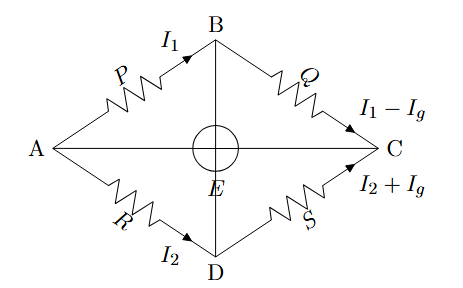
Let the current from the cell be . At junction A, it splits into (through P) and (through R). At junction B, splits into (through G) and (through Q). At junction D, currents and combine to flow through S.
Applying Kirchhoff's Loop Rule to the closed loop ABDA:
Applying Kirchhoff's Loop Rule to the closed loop BCDB:
Step 3: Deriving the Balanced Condition:
The bridge is said to be balanced when there is no current flowing through the galvanometer. This means the potential at point B is equal to the potential at point D ( ).
The condition for balance is .
Substituting into equation (1):
Substituting into equation (2):
Now, divide equation (3) by equation (4):
This is the required balanced condition for a Wheatstone bridge.
About Current Electricity - BIHAR-BOARD-XII
Current Electricity is a vital chapter for BIHAR-BOARD-XII aspirants. Mastering the concepts covered in this chapter is essential for securing a top rank.
By rigorously practicing the previous year questions associated with this chapter, you can identify high-yield topics, understand the examiner's perspective, and boost your confidence during the actual exam.
Frequently Asked Questions
Why focus on Current Electricity PYQs?
Analyzing PYQs for this specific chapter reveals the most frequently tested concepts and the typical complexity of questions, allowing you to tailor your study plan efficiently.
How to best use this analysis?
Review the topic breakdown to see which sub-topics within Current Electricity carry the most weight. Then, tackle the questions iteratively to solidify your understanding.