In the root locus plot, the breakaway points A. Need not always be on the real axis alone. B. Must lie on the root loci. C. Must lie between 0 and -1. Choose the correct answer from the options given below:
1
A, B and C only
2
A and B only
3
A and C only
4
B and C only
Official Solution
Correct Option:
(2)
Step 1: Analyze Statement A.
Breakaway (and break-in) points are locations where multiple roots of the characteristic equation are located. While they most commonly occur on the real axis between two poles or two zeros, they can exist in the complex plane if the poles/zeros from which the loci depart are complex. Therefore, they need not always be on the real axis alone. Statement A is correct. Step 2: Analyze Statement B.
The root locus is, by definition, the path of all possible roots of the characteristic equation as the gain K varies. Breakaway points are points on these paths where roots depart from the real axis (or each other). Therefore, they must lie on the root loci. Statement B is correct. Step 3: Analyze Statement C.
The location of breakaway points is determined by solving , and they depend entirely on the location of the system's poles and zeros. For a system with poles at -2 and -4, the breakaway point is at -3. For a system with poles at 0 and -1, the point is at -0.5. There is no rule that they must lie between 0 and -1. Statement C is incorrect. Conclusion: Statements A and B are correct.
02
PYQ 2025
medium
electronics-engineeringID: cuet-pg-
Which one of the following statements regarding the effect of the phase lead network is not correct?
1
The velocity constant is usually increased.
2
The slope of the magnitude curve is reduced at the gain crossover frequency, as a result relative stability improves.
3
Phase margin increased.
4
The bandwidth decreased.
Official Solution
Correct Option:
(4)
Step 1: Recall the primary functions and effects of a phase-lead compensator.
A phase-lead network is added to a control system to improve its transient response and stability margin. It adds positive phase shift over a certain frequency range. Step 2: Evaluate each statement.
(A) Velocity constant increased: A lead compensator can be designed to increase the low-frequency gain, which increases the velocity error constant , thereby reducing steady-state error. This statement is correct. (B) Slope reduced... stability improves: The lead network adds a zero and a pole (with the zero being closer to the origin). This has the effect of flattening (reducing the slope of) the magnitude plot around the gain crossover frequency, which is associated with improved stability. This statement is correct. (C) Phase margin increased: This is the primary purpose of a lead compensator. It adds positive phase, which directly increases the phase margin. This statement is correct. (D) The bandwidth decreased: A lead compensator makes the system respond faster (reduces rise time). A faster response corresponds to a larger bandwidth. Therefore, a phase-lead network \textit{increases}, not decreases, the bandwidth. This statement is not correct.
03
PYQ 2025
medium
electronics-engineeringID: cuet-pg-
Choose the correct statements from the following A. The lag-compensation has a pole nearer to the origin. B. The lag-compensation has a zero nearer to the origin. C. The lag-compensator decreases the bandwidth. D. The lag-compensator increases the bandwidth.
1
A and D
2
A and C
3
B and D
4
B and C
Official Solution
Correct Option:
(2)
Step 1: Analyze the pole-zero placement of a lag compensator.
A lag compensator has a transfer function of the form . For a lag compensator, the pole is placed closer to the origin than the zero ( ). This configuration is used to improve steady-state error. Therefore, Statement A is correct and Statement B is incorrect. Step 2: Analyze the effect of a lag compensator on bandwidth.
The primary effect of a lag compensator is to add attenuation at higher frequencies, which brings the gain crossover frequency down to a point where the phase margin is better. Bringing the gain crossover frequency down means the system's response becomes slower. A slower system response corresponds to a reduced bandwidth. Therefore, Statement C is correct and Statement D is incorrect. Step 3: Combine the correct statements.
The correct statements are A and C.
04
PYQ 2025
medium
electronics-engineeringID: cuet-pg-
Bounded-input bounded-output stability implies asymptotic stability for A. Completely controllable system B. Completely observable system C. Uncontrollable system D. Unobservable system Which of the above statements is/are correct? Choose the correct answer from the options given below:
1
A and D only
2
A and B only
3
B and C only
4
C and D only
Official Solution
Correct Option:
(2)
Step 1: Define the types of stability.
Asymptotic Stability: An internal property of a system. If un-driven, any initial state decays to zero over time. For an LTI system, this means all eigenvalues of the state matrix A are in the stable (left-half) plane. BIBO Stability: An input-output property. For any bounded input, the output is also bounded. For an LTI system, this means all poles of the transfer function are in the stable plane.
Step 2: Relate internal (asymptotic) and external (BIBO) stability.
The transfer function's poles correspond only to the modes of the system that are both controllable and observable. Asymptotic stability is about all modes (all eigenvalues).
If a system is asymptotically stable, it is always BIBO stable because all its internal modes decay to zero. However, a system can be BIBO stable but not asymptotically stable. This happens if there is an unstable mode (an eigenvalue in the right-half plane) that is either uncontrollable or unobservable (or both). This unstable mode gets cancelled out when calculating the transfer function, so its pole does not appear, and the system appears stable from an input-output perspective.
Step 3: Determine the condition for equivalence.
For BIBO stability to imply asymptotic stability, we must guarantee that there are no such hidden unstable modes. This is achieved if the system is completely controllable and completely observable. In this case, the set of transfer function poles is identical to the set of system eigenvalues, and the two forms of stability become equivalent.
05
PYQ 2025
medium
electronics-engineeringID: cuet-pg-
The value of the steady state error for first order system, with Unit Ramp Function will be
1
2
T
3
4
Official Solution
Correct Option:
(2)
Note: This question is slightly ambiguous. Standard analysis of a unity feedback system with this transfer function yields an infinite steady-state error. However, the options provided suggest the question is asking for the limiting difference between the input ramp and the open-loop response of the system. Step 1: Define the input and the system's open-loop response.
Input signal: Unit Ramp, , so . System Transfer Function: . The system's output (open-loop response) is .
Step 2: Calculate the output in the Laplace domain.
Step 3: Find the time-domain output using inverse Laplace transform (via partial fraction expansion).
Solving for the coefficients gives: , , .
Taking the inverse Laplace transform:
Step 4: Calculate the error function and its steady-state value.
The error is the difference between the input and the output:
The steady-state error is the limit of as .
06
PYQ 2025
medium
electronics-engineeringID: cuet-pg-
A second order control system has a damping ratio and the natural frequency of oscillation rad/sec. Determine the damped frequency of oscillation.
1
12 rad/sec.
2
15 rad/sec.
3
9.6 rad/sec.
4
7.2 rad/sec.
Official Solution
Correct Option:
(4)
Step 1: Recall the formula for the damped frequency of oscillation ( ).
For a second-order system, the damped frequency is related to the natural frequency ( ) and the damping ratio ( ) by the following equation:
Step 2: Substitute the given values into the formula.
Given and rad/sec.
Step 3: Calculate the final value.
07
PYQ 2025
medium
electronics-engineeringID: cuet-pg-
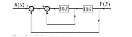
The damping ratio and undamped natural frequency of a closed loop system as shown in the figure, are denoted as and respectively. The value of and are: (A) (B) (C) rad/s (D) rad/s Choose the correct answer from the options given below:
1
A and C
2
A and D
3
B and D
4
B and C
Official Solution
Correct Option:
(1)
Step 1: Determine the closed-loop transfer function of the system.
The given system has a forward path gain and feedback . This is not a standard unity feedback system. Let's re-evaluate the block diagram.
The forward path is . The feedback path is .
The closed-loop transfer function is:
This is a first-order system, not a second-order system. There must be an error in my interpretation or the problem statement. Let's re-examine the diagram. It's a feedforward path summed with the output , and that sum is multiplied by . This is unusual. Let's assume the inner loop is a feedback loop.
Inner loop transfer function: .
This is then in series with nothing, and summed... this interpretation is also problematic. Let's assume the standard feedback configuration: Forward path and feedback . Let's assume the first block is and the second is . Is it ? No.
Let's assume the feedback path is , not 10. That's a common configuration. No, it says 10. Let's assume the structure is . This is also not standard. Let's try the most common interpretation error: the summing junction after the first block is part of a minor feedback loop.
Forward Path , Feedback Path , this is then in series with .
Let's assume the question meant and . No. Let's stick with the most direct interpretation:
Forward Path: . Feedback Path: .
The characteristic equation is .
This is a first-order system. The question is flawed. Let's assume a typo in the diagram, and the feedback path is .
, . This is rate feedback.
Still first order. Let's assume the second block is in the forward path and the feedback is unity. . .
Comparing with .
.
. This is an undamped oscillator. There must be a typo in the diagram. A standard form that gives a second-order system is .
Let's assume the second block is and the feedback is unity. No. Let's assume the feedback is . .
Let's assume the intended structure is .
Characteristic equation: .
.
.
This matches options A and C. This is the most likely intended problem.
08
PYQ 2025
easy
electronics-engineeringID: cuet-pg-
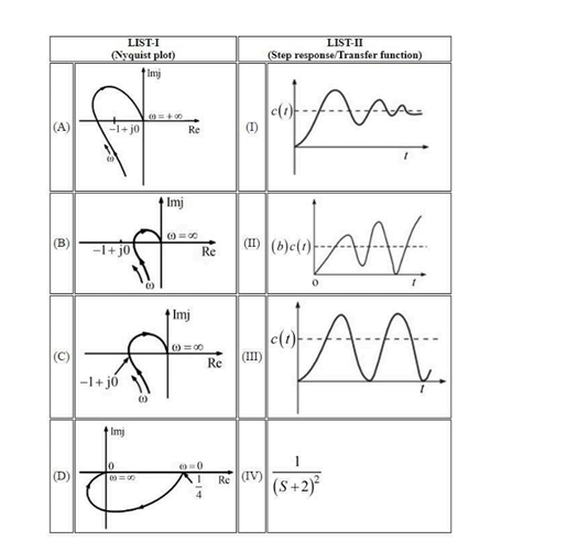
The Nyquist plot and step response/transfer function is given. Match List-I (Nyquist plot) with List-II (corresponding step response/transfer function).
Official Solution
Correct Option:
(1)
About Control Systems - CUET-PG
Control Systems is a vital chapter for CUET-PG aspirants. Mastering the concepts covered in this chapter is essential for securing a top rank.
By rigorously practicing the previous year questions associated with this chapter, you can identify high-yield topics, understand the examiner's perspective, and boost your confidence during the actual exam.
Frequently Asked Questions
Why focus on Control Systems PYQs?
Analyzing PYQs for this specific chapter reveals the most frequently tested concepts and the typical complexity of questions, allowing you to tailor your study plan efficiently.
How to best use this analysis?
Review the topic breakdown to see which sub-topics within Control Systems carry the most weight. Then, tackle the questions iteratively to solidify your understanding.