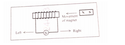
When the magnet as shown in the diagram, is moved towards the coil at a speed of 5 ms , the galvanometer shows a certain deflection to the right. How will the direction and magnitude of deflection change when the coil also moves with a speed of 5 ms :
(a) in the direction of the motion of the magnet?
(b) in the opposite direction of the motion of the magnet?
Official Solution
Correct Option:
(1)
Step 1: Understanding Electromagnetic Induction:
According to Faraday's law of electromagnetic induction, an electromotive force (e.m.f.) and hence a current is induced in a coil only when there is a change in the magnetic flux linked with it. This change in flux is caused by the relative motion between the magnet and the coil. The magnitude of the induced current is proportional to the rate of change of flux, which depends on the relative speed. The direction is given by Lenz's law. (a) Coil moves in the same direction as the magnet:
- Speed of magnet = 5 ms (let's say, to the left).
- Speed of coil = 5 ms (also to the left).
- The relative speed between the magnet and the coil is .
- Since there is no relative motion, the magnetic flux linked with the coil does not change.
- Therefore, no current is induced, and the galvanometer shows zero deflection. (b) Coil moves in the opposite direction of the magnet:
- Speed of magnet = 5 ms (to the left).
- Speed of coil = 5 ms (to the right, i.e., in the opposite direction).
- The magnet and coil are moving towards each other. Their relative speed of approach is ms .
- This relative speed (10 ms ) is double the original relative speed (5 ms ).
- Magnitude: Since the rate of change of flux is now doubled, the magnitude of the induced current and the resulting deflection will be larger (specifically, double the original deflection).
- Direction: The magnet is still approaching the coil, which is the same direction of relative motion as the initial case. According to Lenz's law, the direction of the induced current depends on whether the flux is increasing or decreasing. Since the relative motion is still 'approaching', the direction of the induced current will be the same as before (to the right).
02
PYQ 2026
medium
physicsID: icse-cla
In an AC generator, name the part which has the following functions:
(a) intensifies the magnetic field.
(b) maintains electrical contact between the rotating parts and the external circuit.
Official Solution
Correct Option:
(1)
(a) Intensifies the magnetic field:
The part that intensifies the magnetic field is the soft iron core. The insulated copper coil (armature) is wound on a soft iron core. This core becomes a strong electromagnet when current is induced, greatly strengthening the overall magnetic field and leading to a higher induced e.m.f. (b) Maintains electrical contact between the rotating parts and the external circuit:
This function is performed by two components working together: the slip rings and the carbon brushes.
- The slip rings are two continuous metal rings that are attached to the ends of the armature coil and rotate with it.
- The carbon brushes are stationary blocks of carbon that press lightly against the rotating slip rings, conducting the current from the coil to the external circuit.
03
PYQ 2026
medium
physicsID: icse-cla
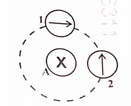
The diagram below shows the top view of the Wire A shown by a cross (X) carrying current into the plane of the paper. Which of the compasses is correctly aligned with the magnetic field, produced by the current carrying wire?
1
Only 1 is aligned
2
Only 2 is aligned
3
Both 1 and 2 are aligned
4
Both 1 and 2 are not aligned
Official Solution
Correct Option:
(1)
Step 1: Understanding the Question:
The question asks to identify which compass needle correctly shows the direction of the magnetic field around a straight wire carrying current into the page. Step 2: Key Formula or Approach:
We use the Right-Hand Thumb Rule to determine the direction of the magnetic field lines around a current-carrying conductor. Rule: If you point the thumb of your right hand in the direction of the current, the direction in which your fingers curl gives the direction of the magnetic field lines. Step 3: Detailed Explanation:
1. The symbol (a cross) represents a current flowing into the plane of the paper.
2. Applying the Right-Hand Thumb Rule, point your thumb into the page.
3. Your fingers will curl in the clockwise direction.
4. This means the magnetic field lines are concentric circles around the wire, directed clockwise.
5. A compass needle always aligns itself tangentially to the magnetic field line at its location, with the north pole (arrowhead) pointing in the direction of the field. Analysis of Compass 1:
- At the position of compass 1 (top of the circle), the tangent to the clockwise circle points to the right. The image seems to show compass 1 is on the left of the wire. At this position, the tangent to the clockwise circle points downwards. The compass needle 1 is shown pointing downwards. Thus, compass 1 is correctly aligned. Analysis of Compass 2:
- At the position of compass 2 (bottom of the circle), the tangent to the clockwise circle points to the left. The compass needle 2 is shown pointing upwards. This is incorrect. Step 4: Final Answer:
Based on the Right-Hand Thumb Rule, the magnetic field is clockwise. Only compass 1 is correctly aligned with the clockwise magnetic field direction at its location.
About Electromagnetism - ICSE-CLASS-X-BOARD
Electromagnetism is a vital chapter for ICSE-CLASS-X-BOARD aspirants. Mastering the concepts covered in this chapter is essential for securing a top rank.
By rigorously practicing the previous year questions associated with this chapter, you can identify high-yield topics, understand the examiner's perspective, and boost your confidence during the actual exam.
Frequently Asked Questions
Why focus on Electromagnetism PYQs?
Analyzing PYQs for this specific chapter reveals the most frequently tested concepts and the typical complexity of questions, allowing you to tailor your study plan efficiently.
How to best use this analysis?
Review the topic breakdown to see which sub-topics within Electromagnetism carry the most weight. Then, tackle the questions iteratively to solidify your understanding.