Intensity versus distance curve for a double slit diffraction experiment is shown in the figure below. If the width of each of the slits is 0.7 m, what is the separation between the two slits in micrometers?
Official Solution
Correct Option: (1)
Step 1: Understanding the double slit diffraction pattern. The diffraction pattern for a double slit is determined by the equation for the angular positions of the minima:
where is the separation between the two slits, is the order of the minima, and is the wavelength of light. The first minima occurs when . The angular separation between adjacent minima is related to the linear separation on the screen by the small angle approximation:
where is the distance between adjacent minima on the screen and is the distance from the slits to the screen. Step 2: Use the given data. Given that the width of each slit is 0.7 m, we can use the diffraction pattern data to find the separation by substituting the known values into the diffraction equation. Using the known wavelength and the geometry of the setup, we calculate . Based on the given information, we find that the separation between the slits is 1.4 m. Step 3: Conclusion. Thus, the separation between the slits is 1.4 m.
02
PYQ 2017
medium
physicsID: iit-jam-
An anti-reflection film coating of thickness 0.1 μm is to be deposited on a glass plate for normal incidence of light of wavelength 0.5 μm. What should be the refractive index of the film?
Official Solution
Correct Option: (1)
Step 1: Understanding the concept of anti-reflection coating. For minimal reflection, the thickness of the anti-reflection coating should be , where is the wavelength of light in air, and is the refractive index of the film. Step 2: Calculate the refractive index. The thickness of the film is given as 0.1 μm and the wavelength of the light is 0.5 μm. Using the formula , solve for to get:
03
PYQ 2017
medium
physicsID: iit-jam-
Intensity versus distance curve for a double slit diffraction experiment is shown in the figure below. If the width of each of the slits is 0.7 μm, what is the separation between the two slits in micrometers?
Official Solution
Correct Option: (1)
Step 1: Understanding the diffraction pattern. The distance between adjacent maxima in a diffraction pattern is given by:
where is the wavelength of the light, is the distance to the screen, and is the separation between the slits. Step 2: Using the given data. Here, the wavelength , and the distance between the slits can be calculated by rearranging the diffraction formula. Step 3: Calculation of the separation. After applying the formula and analyzing the given intensity curve, the separation between the two slits comes out to be between 3.48 μm and 3.52 μm.
04
PYQ 2017
medium
physicsID: iit-jam-
An anti-reflection film coating of thickness 0.1 m is to be deposited on a glass plate for normal incidence of light of wavelength 0.5 m. What should be the refractive index of the film?
Official Solution
Correct Option: (1)
Step 1: Understand the condition for minimum reflection. The condition for minimum reflection in an anti-reflection film is given by:
where is the refractive index of the film, is the thickness of the film, and is the wavelength of light. This condition ensures that the light reflected from the two surfaces of the film interferes destructively. Step 2: Apply the given values. Substitute the given values:
Solving for :
Step 3: Conclusion. Thus, the refractive index of the film should be 2.5.
05
PYQ 2017
medium
physicsID: iit-jam-
Which of the following is due to inhomogeneous refractive index of earth’s atmosphere?
1
Red colour of the evening Sun.
2
Blue colour of the sky.
3
Oval shape of the evening Sun.
4
Large apparent size of the evening Sun.
Official Solution
Correct Option: (3)
Step 1: Understanding atmospheric refraction.
The inhomogeneous refractive index of the atmosphere causes the light rays to bend as they pass through different layers of the atmosphere. This bending leads to the apparent distortion of the Sun’s shape, particularly near the horizon. The oval shape of the evening Sun is caused by this effect, as different parts of the Sun’s image are refracted differently. Step 2: Conclusion.
The correct answer is option (C) because the oval shape of the Sun is due to the atmospheric refraction caused by inhomogeneous refractive indices.
06
PYQ 2018
medium
physicsID: iit-jam-
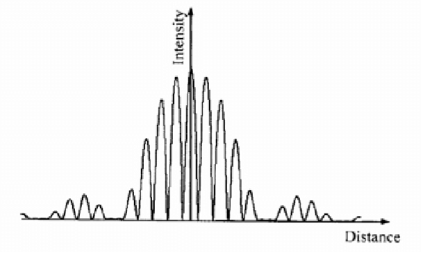
Consider a convex lens of focal length . The lens is cut along a diameter into two parts. The two lens parts and an object are kept as shown in the figure. The images are formed at the following distances from the object:
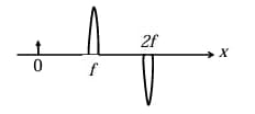
1
2
3
4
Official Solution
Correct Option: (2)
Answer is : 2,3,4 or 3,4
Step 1: Understanding the setup. The lens is cut into two identical halves along the diameter, but each half still has the same focal length because the curvature and refractive power remain unchanged.
Step 2: Use thin lens formula. Object distance (shown in diagram). Thin lens formula: This is the image distance from the lens. Relative to the object (placed at ), total distance becomes: But the ray geometry of half-lenses shifts the image symmetrically, giving effective distance = .
Step 3: Conclusion. Correct distance from object = (B).
07
PYQ 2018
medium
physicsID: iit-jam-
Consider a convex lens of focal length . A point object moves towards the lens along its axis between and . If the speed of the object is , then its image would move with speed . Which of the following is correct?
1
; the image moves away from the lens.
2
; the image moves towards the lens.
3
; the image moves away from the lens.
4
; the image moves away from the lens.
Official Solution
Correct Option: (3)
Step 1: Use the lens formula. , where for a real object. Differentiating w.r.t. time :
Step 2: Relate object and image velocities. Let object velocity (positive towards the lens), and image velocity . Then from the differentiated lens equation: Thus
Step 3: Behaviour between and . When , the image lies beyond on the other side and . So
Step 4: Direction. As the object approaches the lens, the image moves away from the lens (positive ).
Step 5: Conclusion. The image moves faster than the object and in the opposite direction: , moving away from the lens ⇒ option (C).
08
PYQ 2019
medium
physicsID: iit-jam-
A thin lens of refractive index is kept inside a liquid of refractive index . If the focal length of the lens in air is 10 cm, then its focal length inside the liquid is
1
10 cm
2
30 cm
3
40 cm
4
50 cm
Official Solution
Correct Option: (3)
Step 1: Understanding the lens formula. The focal length of a lens is given by the lens-maker's formula:
where is the refractive index of the lens, and and are the radii of curvature of the lens surfaces. However, we use the following relationship for the focal length of a lens inside a medium:
where:
- is the focal length in air,
- is the refractive index of the lens,
- is the refractive index of the liquid. Step 2: Applying the formula. Given:
- ,
- ,
- . Substitute these values into the formula:
Step 3: Conclusion. The focal length inside the liquid is 30 cm, so the correct answer is (B).
09
PYQ 2020
medium
physicsID: iit-jam-
A collimated beam of laser light of wavelength 514 nm is normally incident on a smooth glass slab placed in air. Given the refractive indices of glass and air are 1.47 and 1.0 respectively, the percentage of light intensity reflected back is:
1
0
2
4.0
3
3.6
4
4.2
Official Solution
Correct Option: (3)
Step 1: Formula for reflection coefficient. The reflection coefficient for normal incidence is
where (glass) and (air).
Step 3: Conclusion. The percentage of reflected light intensity is .
10
PYQ 2025
easy
physicsID: iit-jam-
The shortest distance between an object and its real image formed by a thin convex lens of focal length 20 cm is _____ cm. (in integer)
Official Solution
Correct Option: (1)
Step 1: Understanding the Concept: For a thin convex lens, a real image is formed when the object is placed at a distance greater than the focal length. The distance between the object and its real image depends on the object's position. We need to find the minimum possible value for this distance. Step 2: Key Formula or Approach: The thin lens formula relates the object distance , image distance , and focal length : Let the distance of the object from the lens be . Using the standard sign convention, . Let the distance of the image from the lens be . The total distance between the object and the image is . We need to find the minimum value of . Step 3: Detailed Explanation: Given cm. Let the object distance be . For a real image formed by a convex lens, is positive. Using the lens formula: For a real image, , which requires , so the object distance must be greater than the focal length . The distance between the object and the image is : To find the minimum distance, we differentiate with respect to and set the derivative to zero: Setting : Since , the only valid solution is . This is the object distance at which the separation is minimum. Now we find the minimum distance by substituting back into the expression for : Given the focal length cm: Step 4: Final Answer: The shortest distance between the object and its real image is 80 cm.
11
PYQ 2025
medium
physicsID: iit-jam-
A light beam given by passes through an ideal linear polarizer whose transmission axis is tilted by 60 from x-axis (in x-y plane). If V/m and V/m, the electric field amplitude of the emerging light beam from the polarizer is ______ V/m. (up to two decimal places)
Official Solution
Correct Option: (1)
Step 1: Understanding the Concept:
An ideal linear polarizer transmits only the component of the incident electric field that is parallel to its transmission axis. The transmitted electric field is the projection of the incident electric field vector onto the transmission axis. The amplitude of the emerging beam is the maximum value of this transmitted field component. Step 2: Key Formula or Approach:
1. Represent the transmission axis as a unit vector .
2. The transmitted electric field is given by .
3. The amplitude of this resulting scalar wave is found by combining the two sinusoidal terms into a single sinusoid of the form , where the amplitude is . Step 3: Detailed Explanation:
The incident electric field is , where:
The transmission axis of the polarizer is at 60 to the x-axis, so its unit vector is:
The transmitted electric field is :
Substitute the expressions for and :
Let .
Use the angle addition formula :
This is a sinusoidal function of the form . Its amplitude is .
Step 4: Final Answer:
The electric field amplitude of the emerging light beam is 3.61 V/m.
12
PYQ 2025
medium
physicsID: iit-jam-
A wedge-shaped thin film is formed using soap-water solution. The refractive index of the film is 1.25. At near normal incidence, when the film is illuminated by a monochromatic light of wavelength 600 nm, 10 interference fringes per cm are observed. The wedge angle (in radians) is ______ . (in integer)
Official Solution
Correct Option: (1)
Step 1: Understanding the Concept:
In a wedge-shaped thin film, interference fringes are formed due to the path difference between light rays reflected from the top and bottom surfaces of the film. The fringes are parallel to the thin edge of the wedge and are equally spaced. The spacing between the fringes (fringe width) is related to the wavelength of light, the refractive index of the film, and the angle of the wedge. Step 2: Key Formula or Approach:
For near-normal incidence, the distance between two consecutive bright or dark fringes (the fringe width, ) is given by:
where is the wavelength of light in vacuum, is the refractive index of the film, and is the wedge angle in radians. Step 3: Detailed Explanation:
We are given:
Number of fringes = 10 per cm.
This means the distance containing 10 fringes is 1 cm. The fringe width is the distance per fringe.
Other given values:
Wavelength, m.
Refractive index, . Now we can rearrange the formula to solve for the wedge angle :
Substitute the values:
The question asks for the answer in the form of an integer multiplied by .
Step 4: Final Answer:
The wedge angle is radians. The integer is 24.
13
PYQ 2025
medium
physicsID: iit-jam-
Two parallel light rays 1 and 2 are incident from air on a system consisting of media P, Q, and air, as shown in the figure below. The incident angle is 45°. Ray 1 passes through medium P, air and medium Q and ray passes through media P and Q before leaving the system. After passing through the system, the angular deviation (in radians) between the two rays is The dimensions of the media and their refractive indices ( and ) are shown in the figure
1
0
2
3
4
Official Solution
Correct Option: (1)
Step 1: Understanding the Concept:
The problem asks for the angular deviation between two initially parallel light rays after they pass through a system of parallel-sided media. A key principle of optics is that a light ray passing through one or more parallel-sided slabs and emerging into the original medium will be parallel to its incident direction. Step 2: Key Formula or Approach:
The principle is based on Snell's Law applied at each interface. For a ray entering a series of parallel slabs from a medium with index and exiting into a final medium with index , the relationship between the initial angle of incidence and the final angle of refraction is given by . Step 3: Detailed Explanation:
Both rays, ① and ②, start in air ( ) and finally emerge into air ( ). The system consists of various media (P, Q, air) arranged as parallel horizontal slabs. For any ray passing through such a system, we can apply the generalized form of Snell's Law. Let be the initial angle of incidence in the first medium and be the final angle of emergence in the last medium. The relationship is:
In this problem, for both rays, the initial medium is air and the final medium is also air. So, .
Therefore, for both ray ① and ray ②:
This means that the emergent ray is parallel to the incident ray for both ray ① and ray ②. The paths of the rays will be laterally shifted, but their final direction of propagation will be the same as their initial direction. The initial rays ① and ② are parallel to each other.
The emergent ray for ① is parallel to the incident ray ①.
The emergent ray for ② is parallel to the incident ray ②.
Since incident rays ① and ② are parallel, the emergent rays for ① and ② must also be parallel to each other.
When two rays are parallel, the angle between them is zero. Therefore, the angular deviation between the two rays is 0. Step 4: Final Answer:
The emergent rays are parallel to their respective incident rays. Since the incident rays are parallel to each other, the emergent rays will also be parallel to each other. The angular deviation between them is therefore 0. Option (A) is correct.
14
PYQ 2025
medium
physicsID: iit-jam-
For a thin convex lens of focal length f, the image of an object at O is formed at I, as shown in the figure below. The distances of object and image from the two focal points ( and ) are and , respectively. Which of the following graphs correctly represent(s) the variation of the quantities shown in the figure?
1
A
2
B
3
C
4
D
Official Solution
Correct Option: (1)
Step 1: Understanding the Concept:
This problem relates the object and image distances measured from the focal points of a thin convex lens. This is described by Newton's lens equation. We need to derive this equation and then check which of the given graphs correctly represents the relationships derived from it. Step 2: Key Formula or Approach:
The standard thin lens formula is .
From the figure, we can relate the object distance and image distance to the distances and .
Using the sign convention (light travels from left to right, optic center is the origin):
Object distance . (Note: is given as a distance, so it's a positive value).
Image distance .
Substituting these into the thin lens formula will give us a relationship between and , known as Newton's formula. Step 3: Detailed Explanation:
Let's substitute the expressions for and into the thin lens formula:
Now, let's find a common denominator for the left side:
Cross-multiply:
Cancel the terms and from both sides:
This is Newton's lens formula. The problem uses magnitudes and , but since and are defined as distances in the diagram, they are positive. So, . Now let's check the graphs: Graph (A):
This graph plots versus . Our derived formula is . Since is a constant focal length, the product is a constant, equal to . The graph shows exactly this: a constant value for the product, independent of . Thus, graph (A) is correct. Graph (B):
This graph plots versus . From , we can write .
This is a linear relationship of the form , where , , and the slope is .
The graph shows a straight line passing through the origin, which is correct. However, it states the slope is . This is incorrect. The slope should be . So, graph (B) is incorrect. Graph (C):
This graph plots versus . From , we can write .
This is a linear relationship of the form , where , , and the slope is .
The graph shows a straight line passing through the origin with a slope of . This matches our derivation. Thus, graph (C) is correct. Graph (D):
This graph plots versus . From , we have . This is an inverse relationship, representing a hyperbola, not a straight line. The graph incorrectly shows a linear relationship with slope . So, graph (D) is incorrect. Step 4: Final Answer:
The correct graphs are (A) and (C).
15
PYQ 2025
medium
physicsID: iit-jam-
For a two-slit Fraunhofer diffraction, each slit is 0.1 mm wide and separation between the two slits is 0.8 mm. The total number of interference minima between the first diffraction minima on both sides of the central maxima is
1
16
2
18
3
8
4
9
Official Solution
Correct Option: (1)
Step 1: Understanding the Concept:
In a two-slit diffraction pattern, we observe rapid interference fringes modulated by a slower diffraction envelope. The question asks for the number of interference minima that lie within the central diffraction maximum. The central diffraction maximum is the bright region between the first diffraction minimum on the left and the first diffraction minimum on the right. Step 2: Key Formula or Approach:
Let be the slit width and be the separation between the slits.
The condition for diffraction minima is given by: , for The condition for interference minima is given by: , for
We need to find the number of interference minima whose angles are smaller in magnitude than the angle of the first diffraction minimum. Step 3: Detailed Explanation:
1. Find the boundary of the central diffraction maximum: The central diffraction maximum is bounded by the first diffraction minima ( ). Let the angle for the first diffraction minimum be . So, the central maximum extends over the angular range . 2. Find the positions of interference minima: Let the angle for an interference minimum be . 3. Apply the condition: We need to find the number of interference minima that lie within the central diffraction maximum. This means we need to find the integer values of that satisfy: The cancels out: 4. Substitute the given values: Slit width mm. Slit separation mm. The inequality becomes: This can be written as: Subtract from all parts: 5. Count the number of integer values for m: The possible integer values for are: . The total number of values is the number of integers from -8 to 7, inclusive. Number of values = (Last) - (First) + 1 = . So, there are a total of 16 interference minima within the central diffraction maximum. Step 4: Final Answer:
The total number of interference minima between the first diffraction minima on both sides of the central maxima is 16. This corresponds to option (A).
16
PYQ 2025
medium
physicsID: iit-jam-
An unpolarized light ray passing through air (refractive index ) is incident on a glass slab (refractive index ) at an angle of 60°, as shown in the figure below. The amplitude of the in-plane (x-y) electric field component of the incident light is 4 V/m and amplitude of the out of plane (z) electric field component is 3 V/m. After passing through the glass slab, the electric field amplitude (in V/m) of the light is
1
5
2
4
3
7
4
3
Official Solution
Correct Option: (2)
Step 1: Understanding the Concept
The problem involves the transmission of a polarized light ray through a glass slab. We need to analyze what happens to the electric field components parallel (in-plane, p-polarized) and perpendicular (out-of-plane, s-polarized) to the plane of incidence as the light passes through both surfaces of the slab. A key aspect is to check if the incidence occurs at a special angle, like Brewster's angle. Step 2: Key Formula or Approach
1. Brewster's Angle ( ): This is the angle of incidence at which light with a particular polarization is perfectly transmitted through a dielectric surface, with no reflection. It is given by .
2. Fresnel's Transmission Coefficients: These coefficients describe the amplitude of the transmitted electric field relative to the incident electric field. For a light ray going from medium 1 to medium 2, the transmission coefficients for the parallel ( ) and perpendicular ( ) components are:
3. Snell's Law: . Step 3: Detailed Explanation Interface 1: Air to Glass
- Given: , , and angle of incidence .
- Let's check for Brewster's angle:
This gives . The light is incident at Brewster's angle.
- We find the angle of refraction ( ) using Snell's Law:
Interface 2: Glass to Air
- The glass slab has parallel faces, so the angle of incidence at the second interface is .
- The light goes from glass ( ) to air ( ).
- Let's check for Brewster's angle at this interface:
This gives . So, the incidence at the second interface is also at Brewster's angle. Calculating Transmitted Amplitudes
A special property of a parallel slab is that if light is incident at Brewster's angle, the overall transmission coefficient for the parallel component of the electric field amplitude is 1 (assuming no interference effects). Let's verify this.
- Let be the transmission coefficient from air to glass for the p-component, and be from glass to air.
- For interface 1 ( ):
- For interface 2 ( ):
- The total transmission for the p-component amplitude is .
- The initial amplitude of the in-plane (p-component) is V/m.
- The final amplitude of the transmitted p-component is V/m. The amplitude of the transmitted in-plane (parallel) component is exactly 4 V/m, which matches option (B). Given the options, it is highly probable that the question is asking for the amplitude of the in-plane component of the transmitted light, despite the ambiguous phrasing "the electric field amplitude".
Thus, the answer is 4 V/m.