What is a transformer? Describe the energy losses occurring in a transformer.
Official Solution
Correct Option: (1)
Step 1: Definition of a Transformer.
A transformer is an electrical device used to transfer electrical energy between two circuits
through electromagnetic induction. It is mainly used to step up or step down AC voltages in
a power system.
Step 2: Energy Losses in a Transformer.
The main types of energy losses in a transformer are: - **Core Loss (Hysteresis Loss)**:
Caused by the alternating magnetic field in the core, which causes energy loss due to
hysteresis in the material. - **Eddy Current Loss**: Induced currents in the core that result
in energy dissipation as heat. - **Copper Loss**: Losses in the primary and secondary
windings due to the resistance of the wires. - **Leakage Flux Loss**: Losses due to
incomplete magnetic coupling between the primary and secondary windings.
02
PYQ 2023
medium
physicsID: up-board
Write down the phase difference between voltage and current in a pure inductive alternating circuit.
Official Solution
Correct Option: (1)
Step 1: Phase Difference in an Inductive Circuit. In a pure inductive alternating circuit, the current lags the voltage by . The voltage leads the current.
03
PYQ 2023
medium
physicsID: up-board
In an A.C. circuit, potential difference and current are given as,The power consumed in the circuit is:
1
watt
2
10 watt
3
2.5 watt
4
5 watt
Official Solution
Correct Option: (3)
Step 1: Identify RMS values. For voltage: For current: Step 2: Power factor. The phase difference between and is . Step 3: Average power consumed.
Step 4: Conclusion. The power consumed is 2.5 W.
04
PYQ 2023
medium
physicsID: up-board
Write down the relationship between root-mean-square value and peak value of an alternating voltage. In the given circuit, find the value of inductive reactance and the potential difference between the ends of the resistance.
Official Solution
Correct Option: (1)
Step 1: Relationship Between Root-Mean-Square (rms) Value and Peak Value. The root-mean-square (rms) value of an alternating voltage is related to the peak value by:
This relation holds for both current and voltage in an AC circuit. Step 2: Inductive Reactance. The inductive reactance is given by the formula:
where:
- is the frequency of the AC supply, - is the inductance of the coil. Given that , we can calculate if the frequency is provided. Step 3: Potential Difference Across the Resistance. The total impedance in an R-L circuit is given by:
where:
- is the resistance, - is the inductive reactance. The potential difference across the resistance is given by:
where is the current in the circuit, which can be calculated using the rms voltage and the total impedance:
Substitute the values to find the potential difference across the resistance.
05
PYQ 2023
medium
physicsID: up-board
An electron enters the region of magnetic field at an angle of 60° with the speed of . Find the radius of the helical path and the pitch (distance between two consecutive spirals) of the electron beam.
Official Solution
Correct Option: (1)
Step 1: Magnetic Force on the Electron. The magnetic force acting on the electron is given by the formula:
Where:
- is the charge of the electron,
- is the velocity of the electron,
- is the magnetic field,
- is the angle between the velocity and the magnetic field. Step 2: Centripetal Force and Radius. For circular motion, the magnetic force provides the centripetal force, so:
Where is the radius of the helical path and is the mass of the electron. Substitute the known values:
Solving for , we get:
Step 3: Pitch of the Helical Path. The pitch of the helical path is the distance the electron moves along the direction of the magnetic field during one complete revolution. The pitch is given by:
Where is the time period of the electron’s circular motion.
The time period is:
Substitute the values:
Substituting the known values:
Final Answer:
The radius of the helical path is and the pitch of the electron’s path is .
06
PYQ 2023
medium
physicsID: up-board
Resistance , inductance and capacitor are connected in series. The frequency of the alternating current source is and resonant frequency is . Under which condition does the current lag behind the voltage?
1
2
3
4
Official Solution
Correct Option: (2)
Step 1: Understanding the RLC Series Circuit. In a series RLC circuit, the current lags behind the voltage under certain conditions, depending on the relationship between the driving frequency and the resonant frequency . The resonant frequency is given by:
When the driving frequency is less than the resonant frequency, the circuit behaves inductively, and the current lags behind the voltage. Step 2: Analysis of options. - (A) : If the frequency is zero, there is no oscillation, and the current will not be defined as lagging. - (B) : When the frequency is less than the resonant frequency, the inductive reactance dominates, and the current lags behind the voltage. This is the correct answer. - (C) : At resonance, the current and voltage are in phase, meaning there is no lag. - (D) : When the frequency is greater than the resonant frequency, the capacitive reactance dominates, and the current leads the voltage, not lags behind it.
Step 3: Conclusion. The current lags behind the voltage when the frequency of the source is less than the resonant frequency, making option (B) the correct answer.
07
PYQ 2023
medium
physicsID: up-board
From the given A.C. circuit, find out: 
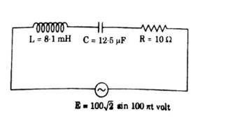
Inductive and capacitive reactance Frequency of the applied voltage in the state of resonance Impedance of the circuit in resonance stage
Official Solution
Correct Option: (1)
Step 1: Identify given values.
Step 2: Inductive reactance.
Step 3: Capacitive reactance.
Step 4: Resonance condition. At resonance, . So, Step 5: Substitution.
Step 6: Reactances at resonance.
Step 7: Impedance at resonance. At resonance, , so impedance is purely resistive: Step 8: Conclusion. (A) , (B) (C)
08
PYQ 2023
medium
physicsID: up-board
In the given circuit, find (i) voltage across resistance, (ii) current in the circuit, (iii) phase difference between voltages across inductance and capacitance.
Official Solution
Correct Option: (1)
Step 1: Identify circuit elements. , (rms value ), inductive reactance , capacitive reactance . Step 2: Net reactance. Since , they cancel each other. Step 3: Impedance.
Step 4: Current in circuit. RMS source voltage . Step 5: Voltage across resistance.
Step 6: Phase difference between and . Since , the voltages are equal but out of phase. Step 7: Conclusion. - Voltage across : - Current: - Phase difference:
09
PYQ 2023
medium
physicsID: up-board
Define the formula for the resonant frequency in a series L-C-R alternating current circuit.
Official Solution
Correct Option: (1)
In a series L-C-R circuit, resonance occurs when the inductive reactance ( ) and capacitive reactance ( ) are equal in magnitude but opposite in phase. The formula for the resonant frequency of a series L-C-R circuit is given by:
where:
- is the inductance in henries (H),
- is the capacitance in farads (F). At this frequency, the impedance of the circuit is purely resistive, and the current reaches its maximum value.
10
PYQ 2023
medium
physicsID: up-board
The equations of current and voltage in a circuit are as follows:Find:
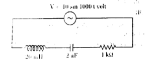
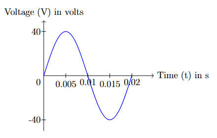
(i) \text{Root mean square value of current}, (ii) \text{Time period}, (iii) \text{Phase difference between current and voltage.}
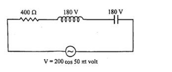
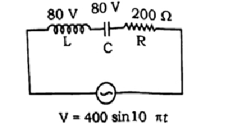
Official Solution
Correct Option: (1)
The equations of current and voltage are given as:
Where: - A (maximum current), - V (maximum voltage), - rad/s (angular frequency), - (phase of current), - (phase of voltage). (i) Root Mean Square Value of Current: The root mean square (rms) value of current is given by: (ii) Time Period: The time period is related to the angular frequency by the formula: (iii) Phase Difference Between Current and Voltage: The phase difference between current and voltage is the difference between their phase angles: Thus, the phase difference between current and voltage is radians (or -60°).
11
PYQ 2023
medium
physicsID: up-board
In the given circuit, calculate: i) Current
ii) Voltage across the resistor iii) Phase difference between L and C
Official Solution
Correct Option: (1)
The given circuit has an AC voltage source with voltage V, an inductor , a capacitor , and a resistor in series. The inductance , and the capacitance . Step 1: Voltage across the components. The voltage across the resistor can be calculated using Ohm's law:
where is the current in the circuit. The total impedance of the series circuit is given by:
where:
- is the inductive reactance, - is the capacitive reactance, - is the angular frequency. Substituting the values:
Now, calculate the total impedance:
Step 2: Current in the circuit. The current can be calculated from the voltage and impedance:
Step 3: Voltage across the resistor. Once the current is calculated, we can use Ohm's law to find the voltage across the resistor:
Step 4: Phase difference. The phase difference between the inductor and the capacitor is given by:
Step 5: Conclusion. Using the above formulas and calculations, we can obtain the current, voltage across the resistor, and the phase difference between the inductor and the capacitor.
12
PYQ 2025
easy
physicsID: up-board
The resistance of 8 ohm and inductive reactance of 6 ohm are connected in series in an alternating current circuit. The impedance of circuit will be :
1
2 ohm
2
14 ohm
3
14 ohm
4
10 ohm
Official Solution
Correct Option: (4)
Step 1: Understanding the Concept:
Impedance (Z) is the total opposition to the flow of alternating current in a circuit. In a series R-L circuit, it is the vector sum of the resistance (R) and the inductive reactance (X ). Step 2: Key Formula or Approach:
The formula for the impedance of a series R-L circuit is:
where R is the resistance and X is the inductive reactance. Step 3: Detailed Explanation:
We are given the following values: Resistance (R) = 8
Inductive reactance (X ) = 6 Substituting these values into the impedance formula:
Step 4: Final Answer:
The impedance of the circuit is 10 ohm.
13
PYQ 2025
easy
physicsID: up-board
A lamp “50 watt and 100 volt” is to be connected to AC mains of 200 volt 50 Hz. Calculate the capacity of condenser required in series of lamp.
Official Solution
Correct Option: (1)
Step 1: Understanding the Problem and Calculating Lamp Parameters:
The lamp is designed to work at 100 V, but the AC source is 200 V. To operate the lamp safely, we must connect a component in series to drop the excess voltage. Here, a capacitor (condenser) is used. The lamp itself behaves as a resistor.
First, let's find the current required by the lamp and its resistance from its ratings. Power of the lamp, W
Voltage rating of the lamp, V The current (RMS) that must flow through the lamp for it to work properly is:
This will be the current flowing through the entire series RC circuit.
The resistance of the lamp is:
Step 2: Analyzing the Series RC Circuit:
We now have a circuit with a resistor (the lamp, R=200 ) and a capacitor (C) connected in series to an AC source. Source voltage, V
Circuit current, A
Frequency, Hz The total impedance (Z) of the circuit can be calculated as:
Step 3: Calculating Capacitive Reactance ( ):
The impedance of a series RC circuit is given by the formula:
where is the capacitive reactance.
We can solve for :
Step 4: Calculating Capacitance (C):
The capacitive reactance is related to the capacitance and frequency by the formula:
Rearranging to solve for C:
Substituting the values:
This is equal to 9.2 microfarads ( F). Step 5: Final Answer:
The required capacity of the condenser is F or 9.2 F.
14
PYQ 2025
hard
physicsID: up-board
Voltage (V) equation in an alternating current circuit is represented by volt. Here t is in second. Draw the time-voltage graph for one cycle with proper scale.
Official Solution
Correct Option: (1)
Step 1: Understanding the Concept: The given equation is for a sinusoidal alternating voltage. We need to identify its key characteristics (amplitude, frequency, time period) to plot its graph accurately for one complete cycle. Step 2: Key Formula or Approach: The standard equation for a sinusoidal AC voltage is , where: is the peak voltage or amplitude. is the angular frequency. The time period (T) is related to by . Step 3: Detailed Explanation: Comparing the given equation with the standard form: Peak Voltage ( ): V. This means the voltage varies between +40 V and -40 V. Angular Frequency ( ): rad/s. Now, we calculate the time period (T) for one complete cycle: To draw the graph, we need some key points in the first cycle (from t=0 to t=0.02 s): At , V. At s, V (Peak). At s, V. At s, V (Trough). At s, V. Step 4: Graph:
15
PYQ 2025
medium
physicsID: up-board
Describe a series L, C, R resonant circuit.
Official Solution
Correct Option: (1)
A series L, C, R resonant circuit consists of three basic components connected in series: an inductor (L), a capacitor (C), and a resistor (R). In such a circuit, the total impedance of the circuit is affected by the frequency of the applied AC signal. The behavior of the circuit changes as the frequency varies, and resonance occurs at a specific frequency known as the resonant frequency. Impedance of the Series LCR Circuit:
The total impedance of a series L, C, R circuit is given by: where:
- is the resistance,
- is the inductance,
- is the capacitance,
- is the angular frequency of the AC signal. At resonance, the inductive reactance and the capacitive reactance cancel each other out, and the total impedance of the circuit becomes purely resistive: Thus, at resonance, the impedance is minimized, and the current in the circuit reaches its maximum value. Resonant Frequency:
The resonant frequency is the frequency at which the inductive and capacitive reactances are equal in magnitude but opposite in sign. At this frequency, the circuit exhibits purely resistive behavior, and the impedance is equal to the resistance . The resonant frequency is given by: At resonance, the voltage across the inductor and the capacitor is maximum, while the total impedance of the circuit is at a minimum. Power at Resonance:
At resonance, the power delivered to the circuit is maximized. The power in a series LCR circuit is given by: where is the current through the circuit. At resonance, the current reaches its maximum value, and the power dissipated in the resistor is at its peak.
16
PYQ 2025
medium
physicsID: up-board
The peak voltage in a 220 volt A.C. source is
1
220 V
2
about 160 V
3
about 310 V
4
440 V
Official Solution
Correct Option: (3)
Step 1: Understanding the Concept:
In AC (Alternating Current) circuits, the standard voltage rating (like the 220 V for household supply) refers to the RMS (Root Mean Square) value, not the peak or maximum voltage. The RMS value is a kind of average voltage that gives the same heating effect as a DC voltage of the same value. The peak voltage is the maximum value the voltage reaches during its sinusoidal cycle.
Step 2: Key Formula or Approach:
The relationship between the peak voltage ( or ) and the RMS voltage ( ) for a sinusoidal AC source is given by:
or
Step 3: Detailed Explanation:
We are given the RMS voltage of the AC source:
We need to find the peak voltage, .
Using the formula:
Substitute the given value:
We know that the value of is approximately 1.414.
This value is approximately 310 V.
Step 4: Final Answer:
The peak voltage in a 220 volt A.C. source is about 310 V.
17
PYQ 2025
medium
physicsID: up-board
In the given figure, LCR circuit is shown. Voltage of the alternating current source is volt. Calculate for the circuit:
Official Solution
Correct Option: (1)
(i) Total impedance The total impedance of an L-C-R series circuit is given by: where:
- is the resistance,
- is the inductive reactance,
- is the capacitive reactance. Given:
- ,
- ,
- (since the frequency ). First, calculate and : Now, substitute these values into the impedance formula: So, the total impedance is . (ii) Power Factor: The power factor (PF) in a series L-C-R circuit is given by: where:
- ,
- . So, the power factor is: (iii) Peak Value of Current: The peak current in the circuit is given by: where:
- is the peak voltage,
- is the total impedance. So, the peak value of the current is:
18
PYQ 2025
medium
physicsID: up-board
What is meant by resonant circuit? Write down the required condition for the L-C-R series resonant circuit and expression for the frequency in resonant condition.
Official Solution
Correct Option: (1)
Resonant Circuit: A resonant circuit, also called a tuned circuit, is an electrical circuit that resonates at a particular frequency, called the resonant frequency. In such a circuit, the inductive reactance ( ) and capacitive reactance ( ) are equal and cancel each other out, resulting in a minimum impedance. Condition for Resonance in L-C-R Series Circuit: In a series L-C-R circuit, resonance occurs when the inductive reactance and capacitive reactance are equal in magnitude but opposite in phase. The condition for resonance is: where:
- is the inductive reactance,
- is the capacitive reactance,
- is the angular frequency ( ),
- is the inductance,
- is the capacitance. At resonance, , so: Solving for the angular frequency at resonance: The resonant frequency is then:
19
PYQ 2025
medium
physicsID: up-board
What is meant by the wattless current?
Official Solution
Correct Option: (1)
A wattless current refers to an alternating current (AC) that does not result in the transfer of real power to the load. This phenomenon occurs in an AC circuit when the current and voltage are out of phase by 90 degrees. The power consumed in such a circuit is zero because the energy supplied by the source is returned to the source in each cycle. This situation typically happens in circuits that are purely reactive (either capacitive or inductive), where the impedance is entirely due to inductance or capacitance. When the voltage and current are 90 degrees out of phase, the power factor is zero, and no real power is delivered to the load. The formula for the power in an AC circuit is given by: Where is the power, and are the root mean square values of voltage and current, and is the phase difference between the voltage and current. When , , which results in zero power (wattless current). This happens when the circuit consists purely of reactive elements (like inductors and capacitors), where the voltage and current are constantly changing direction and energy alternates back and forth between the source and the reactive components.
20
PYQ 2025
medium
physicsID: up-board
Three ac circuits are shown in the figures with equal currents. Explain with reason, if the frequency of the voltage is increased then what will be the effect on the currents in them. \includegraphics[width=0.5\linewidth]{image4.png}
Official Solution
Correct Option: (1)
The three types of circuits given are:
1. A resistive circuit ( ),
2. An inductive circuit ( ),
3. A capacitive circuit ( ). Resistive Circuit:
In a purely resistive circuit, the current is related to the applied voltage by Ohm's law: Where:
- is the voltage across the resistor,
- is the resistance. In a resistive circuit, the current is independent of frequency. Therefore, increasing the frequency of the voltage will not affect the current in a purely resistive circuit. Inductive Circuit:
In a purely inductive circuit, the current lags the voltage by , and the impedance is given by: Where:
- is the angular frequency ( ),
- is the inductance,
- is the frequency of the voltage. As the frequency increases, the inductive reactance increases, which causes the impedance to increase. According to Ohm's law for AC circuits, the current decreases as the impedance increases. Therefore, increasing the frequency decreases the current in an inductive circuit. Capacitive Circuit:
In a purely capacitive circuit, the current leads the voltage by , and the impedance is given by: Where:
- is the capacitance,
- is the frequency of the voltage. As the frequency increases, the capacitive reactance decreases, which causes the impedance to decrease. According to Ohm's law, as the impedance decreases, the current increases. Therefore, increasing the frequency increases the current in a capacitive circuit. Thus, the effect of increasing frequency on the current in the three circuits is:
- In the resistive circuit, the current remains unchanged.
- In the inductive circuit, the current decreases.
- In the capacitive circuit, the current increases.
21
PYQ 2025
medium
physicsID: up-board
What is meant by wattless current?
Official Solution
Correct Option: (1)
Wattless current refers to the current that flows in an AC circuit when the voltage and current are out of phase with each other by 90 degrees. This happens in circuits that contain purely inductive or purely capacitive elements. In such cases, the power consumed by the circuit is zero because the current and voltage are not in phase, meaning that the energy supplied to the circuit is stored and returned (in the case of inductance or capacitance) without being dissipated as heat. For example, in a purely inductive circuit, the current lags the voltage by 90° and the power factor is zero, meaning no real power is consumed. This results in wattless current, as the average power over a complete cycle is zero.
22
PYQ 2025
medium
physicsID: up-board
The voltage and current of an ac circuit are represented as volt and mA respectively. The power dissipated in the circuit is:
1
watt
2
2.5 watt
3
0.25 watt
4
25 watt
Official Solution
Correct Option: (2)
The instantaneous power dissipated in an AC circuit is given by the formula: Where: - is the maximum voltage, - is the maximum current, - is the phase difference between the voltage and current. From the given expressions: - , so volts, - , so mA or A, - The phase difference . Now, substitute these values into the power formula: Since , we get: Thus, the correct answer is option (B) 2.5 watt.
23
PYQ 2025
medium
physicsID: up-board
In A.C. circuits, what is the difference between impedance and resistance? Write the formula for power factor in L-C-R circuit.
Official Solution
Correct Option: (1)
Impedance vs. Resistance: In A.C. circuits, the key difference between impedance and resistance is as follows: 1. Impedance (Z): Impedance is the total opposition that a circuit offers to the flow of alternating current (A.C.). It includes both resistance and reactance. It is a complex quantity and is expressed as: where: - is the resistance, - is the reactance, which is further divided into inductive reactance and capacitive reactance . 2. Resistance (R): Resistance is the opposition to the flow of current in a circuit due to the material and dimensions of the conductor. It only depends on the physical properties of the material and is independent of frequency. 3. Key Differences: - Resistance is a real quantity that only depends on the nature of the material and temperature. - Impedance is a complex quantity, and it accounts for both resistance and reactance in the circuit. Reactance varies with frequency, and hence, impedance changes with the frequency of the A.C. supply. The formula for the power factor in an L-C-R circuit is given by: where is the phase difference between the applied voltage and the current. The power factor is a measure of how effectively the current is being converted into useful power. The power factor can also be expressed in terms of impedance and resistance as: Explanation: - When the power factor is 1, the current and voltage are in phase, and the circuit behaves like a purely resistive circuit.
- When the power factor is less than 1, the circuit contains reactance, and the current lags behind the voltage in an inductive circuit or leads the voltage in a capacitive circuit.
24
PYQ 2025
medium
physicsID: up-board
In an alternating circuit, the reading of the voltmeter is 220 V. Write the peak value of the voltage.
Official Solution
Correct Option: (1)
In an alternating current (AC) circuit, the voltmeter typically measures the root mean square (RMS) value of the voltage, which is a statistical measure of the magnitude of the varying voltage. The RMS value of voltage is related to the peak voltage (maximum instantaneous voltage) by the following relationship: Where:
- is the RMS value of the voltage,
- is the peak (maximum) value of the voltage. This formula implies that the RMS value is approximately 0.707 times the peak voltage. Now, we are given that the RMS value of the voltage, , is 220 V. To find the peak voltage , we can rearrange the formula as: Substitute the given value of into the equation: Since , we get: Thus, the peak value of the voltage is approximately .
25
PYQ 2025
easy
physicsID: up-board
The peak value of an alternating current is 14.14 Amp., and its frequency is 50 Hz. Draw current-time graph for two cycles. Find r.m.s. value of current. What time will the current take to reach the peak value starting from zero ?
Official Solution
Correct Option: (1)
26
PYQ 2025
medium
physicsID: up-board
What is meant by Wattless current? A capacitor of 15 F is connected to an AC source of 220 V and 50 Hz. Find out reactance of circuit and rms value of AC current.
Official Solution
Correct Option: (1)
Meaning of Wattless Current:
Wattless current is the component of an alternating current in a circuit that does not contribute to the average power consumed over a full cycle. The average power in an AC circuit is given by , where is the phase angle between the voltage and current.
If the phase angle is 90 (as in a purely inductive or purely capacitive circuit), then . This makes the average power consumed zero. The current that flows in such a circuit is called wattless current because it flows without any net dissipation of power. It corresponds to the component of current that is in quadrature (90 out of phase) with the voltage. Calculations:
Step 1: Understanding the Concept and Formulas:
We have a purely capacitive AC circuit. We need to find the capacitive reactance ( ), which is the opposition to the current flow, and then use Ohm's law for AC circuits to find the RMS current ( ).
\begin{itemize} \item Capacitive Reactance: \item RMS Current:
\end{itemize}
Step 2: Detailed Explanation:
We are given:
\begin{itemize} \item Capacitance, . \item RMS Voltage, . \item Frequency, .
\end{itemize}
Part 1: Calculate the Reactance ( ) of the circuit
Using :
Part 2: Calculate the RMS value of AC current ( )
Step 3: Final Answer:
The reactance of the circuit is approximately 212.2 , and the rms value of the AC current is approximately 1.04 A.