Give the relationship of temperature with the resistance and resistivity of a conductor. Define the temperature coefficient of the resistance and give its unit.
Official Solution
Correct Option: (1)
Step 1: Relationship Between Temperature and Resistance. The resistance of a conductor at a temperature is related to its resistance at a reference temperature by:
where:
- is the resistance at the reference temperature , - is the temperature coefficient of resistance, - is the temperature. Step 2: Relationship Between Temperature and Resistivity. The resistivity of a conductor also depends on temperature, and it is given by:
where:
- is the resistivity at the reference temperature . Step 3: Temperature Coefficient of Resistance. The temperature coefficient of resistance is a constant that indicates how much the resistance changes with temperature. It is defined as:
Its unit is .
02
PYQ 2023
medium
physicsID: up-board
Explain the principle of potentiometer. Why is it superior to a voltmeter? How will you compare the e.m.f. of two cells by potentiometer? Explain by drawing a relevant circuit diagram.
Official Solution
Correct Option: (1)
Step 1: Principle of Potentiometer. A potentiometer is an instrument used to measure the potential difference (voltage) across two points in a circuit. The working principle is based on the fact that the potential difference is directly proportional to the length of the wire through which the current flows. A uniform wire of known resistance is used, and the voltage drop along the wire is measured using a galvanometer. The principle is:
where is the potential difference, is the current through the wire, is the resistance of the wire, and is the length of the wire.
Step 2: Why Potentiometer is Superior to a Voltmeter. - A voltmeter measures the potential difference directly by drawing current, which can alter the voltage in the circuit. - A potentiometer, on the other hand, does not draw current from the circuit under test, so it does not alter the potential difference, providing more accurate measurements.
Step 3: Comparing e.m.f. of Two Cells Using a Potentiometer. To compare the e.m.f. of two cells using a potentiometer, we use the following method: 1. Connect the two cells in separate circuits with the same current through the potentiometer. 2. Adjust the sliding contact to measure the potential drop across each cell. 3. The e.m.f. of the cells can be compared by the lengths of the wire that correspond to the potential difference for each cell.
Step 4: Circuit Diagram. The circuit diagram for comparing the e.m.f. of two cells using a potentiometer is shown below:
03
PYQ 2023
medium
physicsID: up-board
e.m.f. of a cell is 1.5 volt and internal resistance is . On connecting the cell with an external resistance of , what will be the potential difference at the terminals of the cell?
Official Solution
Correct Option: (1)
Step 1: Total Resistance in the Circuit. The total resistance is the sum of the internal resistance of the cell and the external resistance: Step 2: Current in the Circuit. Using Ohm's law, the current in the circuit is given by: Step 3: Potential Difference Across the External Resistance. The potential difference across the external resistance is given by: Step 4: Conclusion. The potential difference at the terminals of the cell is:
04
PYQ 2023
medium
physicsID: up-board
On what factors does the internal resistance of a cell depend?
Official Solution
Correct Option: (1)
Step 1: Definition. Internal resistance of a cell is the opposition offered by the electrolyte and electrodes to the flow of charge inside the cell. Step 2: Factors affecting internal resistance. 1. Distance between electrodes: larger distance higher resistance. 2. Area of electrodes: larger area lower resistance. 3. Nature and concentration of electrolyte: higher conductivity lower resistance. 4. Temperature: increase in temperature generally decreases resistance due to better ionic mobility. Step 3: Conclusion. Thus, internal resistance is not fixed but varies with physical and chemical conditions.
05
PYQ 2023
medium
physicsID: up-board
Draw circuit diagram of Wheatstone’s bridge. Which are its conjugate arms?
Official Solution
Correct Option: (1)
Step 1: Wheatstone’s bridge principle. It is based on the principle of null deflection, where no current flows through the galvanometer if the bridge is balanced. Step 2: Circuit diagram. The bridge has four resistors , , , and connected in a quadrilateral. A galvanometer is connected between two opposite corners, and a battery between the remaining two corners. Step 3: Conjugate arms. Conjugate arms are opposite pairs: (P, Q) with (R, S). Specifically, AB and CD are conjugate arms; AD and BC are also conjugate arms. Step 4: Conclusion. Wheatstone’s bridge works on balancing ratios of conjugate arms.
06
PYQ 2023
medium
physicsID: up-board
What is meant by shunt and mention its one use in electrical circuit?
Official Solution
Correct Option: (1)
Step 1: Meaning of shunt. A shunt is a very small resistance connected in parallel with a galvanometer or other instruments. Step 2: Function. It allows most of the current to bypass the galvanometer, protecting it from high current. Step 3: Use. By connecting a shunt across a galvanometer, it can be converted into an ammeter for measuring large currents. Step 4: Conclusion. Thus, shunts are protective and functional elements in measurement circuits.
07
PYQ 2023
medium
physicsID: up-board
Show that represents resistance.
Official Solution
Correct Option: (1)
Step 1: Dimensions of Henry (H). 1 Henry = = Step 2: Dimensions of Farad (F). 1 Farad = Step 3: Ratio Henry/Farad.
In the given circuit, calculate the current in each resistance.
Official Solution
Correct Option: (1)
Step 1: Identify the circuit. The circuit is a Wheatstone-like bridge with three resistors of each and two batteries , . Step 2: Apply Kirchhoff’s Current Law (KCL). Let currents be through AB, through DC, and through AC. At node A: Step 3: Apply Kirchhoff’s Voltage Law (KVL). Loop (A–B–C–A): Loop (A–C–D–A): Step 4: Solve equations. From (1): From (2): Using KCL: So, , , . Step 5: Conclusion. Thus, , , .
09
PYQ 2023
medium
physicsID: up-board
The drift velocity of free electrons is on passing current in a conducting wire. Drift velocity of electrons in the same wire having twice the radius and current will be:
1
2
3
4
Official Solution
Correct Option: (3)
Step 1: Formula for drift velocity. where . Step 2: Compare two cases. Initial case: New case (radius , current ): Step 3: Conclusion. Hence the correct answer is (C) .
10
PYQ 2023
medium
physicsID: up-board
What is meant by shunt?
Official Solution
Correct Option: (1)
Step 1: Understanding shunt. A galvanometer can measure only small currents. To measure larger currents, a low resistance is connected parallel to it. Step 2: Function. The shunt allows most of the current to bypass the galvanometer, protecting it from high current. Step 3: Conclusion. Thus, a shunt is a low resistance used for extending the range of a galvanometer.
11
PYQ 2023
medium
physicsID: up-board
What is Kirchhoff’s First Law for the electrical circuit?
Official Solution
Correct Option: (1)
Step 1: Recall Kirchhoff’s current law (KCL). At any junction in an electric circuit, the total current entering is equal to the total current leaving. Step 2: Mathematical expression.
Step 3: Conclusion. This is Kirchhoff’s First Law.
12
PYQ 2023
medium
physicsID: up-board
Following are the resistances of the four sides of a Wheatstone bridge: AB = 100 , BC = 10 , CD = 5 , DA = 60 ; resistance of galvanometer . Find the value of the current .
Official Solution
Correct Option: (1)
Step 1: Wheatstone Bridge Condition. In a Wheatstone bridge, the bridge is said to be balanced when the ratio of resistances in the two arms of the bridge are equal:
where:
- and are the resistances in one arm (AB and BC),
- and are the resistances in the other arm (CD and DA). Step 2: Given Values. From the problem:
- ,
- ,
- ,
- . Step 3: Finding the Value of . The current is the current passing through the galvanometer. The Wheatstone bridge is not balanced in this case because the ratio of resistances does not satisfy the condition for balance:
Thus, there will be a current through the galvanometer. To find the current , we apply Kirchhoff’s current law and use the potential difference across the galvanometer to calculate the current. The detailed solution involves solving the system of equations using Kirchhoff’s laws, which is beyond the basic scope here. However, the current through the galvanometer can be found by solving these equations. Step 4: Conclusion. The current depends on the potential difference across the bridge and the resistances involved, and it can be solved using Kirchhoff’s laws for this non-balanced Wheatstone bridge.
13
PYQ 2023
medium
physicsID: up-board
The resistance of wire AB as shown in the figure is and of potential difference is applied across it. Resistance of voltmeter is . The point C is at one-fourth distance from the point A. What is the reading of the voltmeter?
Official Solution
Correct Option: (1)
Step 1: Understanding the Circuit. The resistance of the wire AB is , and a potential difference of is applied across it. The voltmeter with a resistance of is connected between point A and point C. Point C is at one-fourth the distance from point A. Thus, the resistance between point A and point C is of the total resistance . Step 2: Calculating the Resistance Between A and C. The resistance between points A and C is: Step 3: Applying the Potential Divider Rule. The voltage across the resistance can be found using the potential divider rule. The total resistance in the circuit is the sum of and the voltmeter resistance : The voltage across the voltmeter is then: Step 4: Conclusion. Thus, the reading of the voltmeter is approximately .
14
PYQ 2023
medium
physicsID: up-board
What is the effect on the null deflection length on decreasing the value of potential gradient in the wire of potentiometer?
Official Solution
Correct Option: (1)
Step 1: Understanding Potentiometer. A potentiometer is a device used to measure the potential difference by comparing it with a known reference voltage. The null deflection length is the length of the wire over which the potential gradient is balanced by the reference voltage.
Step 2: Effect of Decreasing Potential Gradient. The potential gradient is defined as the potential difference per unit length of the wire. If the potential gradient is decreased, it means that for a given length of wire, the potential difference is smaller. To achieve null deflection, the length of the wire required will increase. Thus, the null deflection length increases when the potential gradient decreases.
Step 3: Conclusion. Decreasing the potential gradient will increase the null deflection length.
15
PYQ 2023
medium
physicsID: up-board
Resistance of a wire is . The radius of the wire is halved on stretching it. Find out the new resistance of the wire.
Official Solution
Correct Option: (1)
Step 1: Resistance of a Wire. The resistance of a wire is given by the formula:
where is the resistivity of the material, is the length of the wire, and is the cross-sectional area of the wire. Step 2: Effect of Stretching the Wire. When the wire is stretched, its length increases, and its radius decreases. If the radius is halved, the cross-sectional area , which is proportional to the square of the radius ( ), will decrease by a factor of 4. The resistance is directly proportional to the length and inversely proportional to the area. If the length increases by a factor of (since stretching the wire increases the length), and the area decreases by a factor of 4, the new resistance can be calculated as: Step 3: Conclusion. The new resistance of the wire is .
16
PYQ 2023
medium
physicsID: up-board
Equivalent resistance of three identical resistors in series is and in parallel it is . If , then the minimum possible value of is:
1
2
3
3
4
9
Official Solution
Correct Option: (2)
Step 1: Equivalent Resistance in Series and Parallel. For three identical resistors , the resistance in series is: The resistance in parallel is: Step 2: Relating and . We are given that . Substituting the expressions for and , we get: Step 3: Solving for . Simplifying the equation: Step 4: Conclusion. Therefore, the minimum possible value of is , so the correct answer is (D).
17
PYQ 2023
medium
physicsID: up-board
Define drift velocity of free electrons and write the relation between drift velocity and current density.
Official Solution
Correct Option: (1)
Step 1: Definition of drift velocity. Drift velocity is the average velocity of free electrons in a conductor due to an applied electric field. It is the net velocity that the electrons acquire under the influence of the electric field, superimposed on their random thermal motion. Step 2: Relation between drift velocity and current density. The relation between drift velocity and current density is given by Ohm's law in terms of electron drift:
where:
- is the current density (in A/m²),
- is the number of free electrons per unit volume,
- is the charge of an electron (approximately ),
- is the drift velocity (in m/s). Step 3: Conclusion. The drift velocity is directly related to the current density by the equation .
18
PYQ 2023
medium
physicsID: up-board
The net resistance of an ammeter should be small to ensure that:
1
it does not get overheated
2
it does not draw excessive current
3
it can measure large currents
4
it does not appreciably change the current to be measured
Official Solution
Correct Option: (4)
Step 1: Understanding the function of an ammeter. An ammeter is used to measure current, and it is connected in series with the circuit. To avoid altering the current in the circuit, the ammeter's resistance should be as small as possible.
Step 2: Conclusion. The correct answer is ( because a small resistance ensures that the ammeter does not significantly affect the current it is measuring.
19
PYQ 2023
medium
physicsID: up-board
Unit of electric flux is :
1
Nm C
2
Nm C
3
Vm
4
NmC
Official Solution
Correct Option: (2)
Step 1: Definition of Electric Flux. Electric flux is defined as the product of electric field and the area through which the field lines pass, i.e., . The unit of electric field is (Newton per Coulomb) and area is measured in , so the unit of electric flux becomes , which is equivalent to .
Step 2: Conclusion. Hence, the correct unit of electric flux is , corresponding to option .
20
PYQ 2023
medium
physicsID: up-board
Draw a ray diagram for a reflecting telescope. Explain its working and compare it
with a refracting telescope.
Official Solution
Correct Option: (1)
Step 1: Ray Diagram for Reflecting Telescope. In a reflecting telescope, a concave mirror is used to gather and focus light. The diagram is shown below:
Step 2: Working of a Reflecting Telescope. In a reflecting telescope: 1. Light from a distant object enters the telescope and strikes the concave mirror. 2. The concave mirror reflects the light and focuses it at the focal point. 3. The eyepiece lens is placed at the focal point, and it magnifies the image formed by the mirror.
Step 3: Comparison with Refracting Telescope. In a refracting telescope, lenses are used instead of mirrors. The light enters the objective lens, which forms an image. This image is then magnified by the eyepiece lens. Unlike the reflecting telescope, the refracting telescope uses the lens’s refraction instead of reflection.
Final Answer: A reflecting telescope uses a concave mirror to gather and focus light, while a refracting telescope uses lenses. Reflecting telescopes are generally preferred in astronomy due to the absence of chromatic aberration.
21
PYQ 2023
medium
physicsID: up-board
Derive the formula for the determination of internal resistance of a cell with the help of a potentiometer.
Official Solution
Correct Option: (1)
Step 1: Principle of potentiometer. The potential difference across any length of the potentiometer wire is directly proportional to its balancing length. Step 2: First observation (no external resistance). - The cell is connected directly to the potentiometer. - Let the balancing length be . - Then the emf of the cell is: Step 3: Second observation (with external resistance R). - Now the cell is connected across a resistance . - The potential difference across the cell (terminal voltage) is: - Let the new balancing length be . - Then, Step 4: Ratio of lengths. Substitute : Step 5: Solve for .
Step 6: Conclusion. The internal resistance of the cell is:
22
PYQ 2023
medium
physicsID: up-board
Find the currents through the resistors , and with the help of the given circuit. Internal resistances of the cells are negligible.
Official Solution
Correct Option: (1)
Step 1: Identify given values. Two batteries: (with ), (with ). Step 2: Apply Kirchhoff’s current law (KCL). At the common junction: Step 3: Apply Kirchhoff’s voltage law (KVL). Loop 1 (with and ): Loop 2 (with and ): Step 4: Use current relation. . Substituting into (1): Step 5: Solve equations (2) and (3). From (2): From (3): Subtract equations: Substitute in (2): Negative sign means actual direction is opposite to assumed. So, Thus, Step 6: Final Answer. Hence, actual directions of and are opposite to assumed. Magnitudes: ---
23
PYQ 2023
medium
physicsID: up-board
The circuit diagram of a balanced meter bridge is shown in the figure. The balanced point is obtained at from the end A. When a resistor is joined in series with , the balanced point is obtained at from the end B. Find the values of and .
Official Solution
Correct Option: (1)
Step 1: Balanced bridge condition.
Step 2: First case (without extra resistor). . Step 3: Second case (with 10 in series with ). Balanced point at from B . Step 4: Solve equations (1) and (2). From (1): Substitute in (2): Correction check: Let's recalc carefully: Then, from (3): Step 5: Final Answer. ---
24
PYQ 2023
medium
physicsID: up-board
The length of a wire of resistance is three times the length on stretching it. Now the wire is cut into three equal parts and then they are joined in an electrical circuit as shown in the figure. Find out the total resistance of the combination between A and B.
Official Solution
Correct Option: (1)
Step 1: Effect of stretching on resistance. Resistance of a wire: If the wire is stretched to 3 times its original length, then and volume remains constant. So, Step 2: New resistance of wire. Given original resistance = . Step 3: Cutting into 3 equal parts. When cut into 3 equal parts: Step 4: Analyze circuit. - The top two resistors (each ) are in series: - The bottom resistor is . - These two branches are in parallel. Step 5: Equivalent resistance. ⚠ Correction: Let’s carefully recalc — Wait: , . So, Final answer: . Step 6: Conclusion. The total resistance between A and B is .
25
PYQ 2023
hard
physicsID: up-board
Write the principle of Wheatstone's Bridge. Find the current measured by the ammeter in the given circuit diagram.
Official Solution
Correct Option: (1)
Step 1: Principle of Wheatstone's Bridge. Wheatstone's bridge is used to measure an unknown resistance by balancing two legs of a bridge circuit. The principle of the Wheatstone bridge is that when the bridge is balanced, the ratio of resistances in one leg is equal to the ratio of resistances in the other leg. Mathematically, this is given by:
where and are the resistances in the four arms of the bridge. Step 2: Analyzing the given circuit. In the given circuit diagram, the resistances are: , , and the ammeter is placed in one of the branches of the bridge. Given that the Wheatstone bridge is balanced, the current measured by the ammeter will be zero when the bridge is balanced, meaning there will be no current flowing through the ammeter in the ideal balanced condition. Step 3: Conclusion. In the balanced Wheatstone bridge, the current measured by the ammeter is zero. However, if the bridge is unbalanced, the current can be calculated using the formula:
where and is the total resistance of the circuit.
26
PYQ 2023
medium
physicsID: up-board
The equivalent resistance of the network shown in figure between A and B is:
1
10
2
20
3
5
4
15
Official Solution
Correct Option: (4)
Step 1: Understanding the arrangement of resistors. The two 10 resistors are connected in parallel. The formula for the equivalent resistance of two resistors in parallel is given by:
Substituting , we get:
Step 2: Conclusion. The equivalent resistance of the network is , so the correct answer is (.
27
PYQ 2023
medium
physicsID: up-board
Explain both the laws of Kirchhoff of electrical circuits.
Official Solution
Correct Option: (1)
Kirchhoff’s First Law (Junction Rule): Kirchhoff's first law states that the total current entering a junction (or node) in an electric circuit is equal to the total current leaving the junction. This law is based on the principle of conservation of electric charge. Where: - : Current flowing into the junction - : Current flowing out of the junction Kirchhoff’s Second Law (Loop Rule): Kirchhoff’s second law states that the algebraic sum of the potential differences (voltages) in any closed loop or mesh of a circuit is always zero. This law is based on the conservation of energy. Where: - : Electromotive force (emf) - : Current flowing through elements of the loop - : Resistance in each segment of the loop This means that the total energy supplied in a closed loop is equal to the total energy used.
28
PYQ 2023
medium
physicsID: up-board
What are meant by ohmic and non-ohmic resistances? Draw the graph between voltage and current for a non-ohmic circuit and define dynamic resistance.
Official Solution
Correct Option: (1)
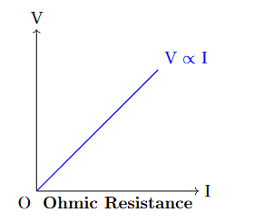
- **Ohmic Resistance:** Ohmic resistance refers to the type of resistance exhibited by materials that follow Ohm's Law, which states that the current passing through a conductor is directly proportional to the voltage applied across it, with the proportionality constant being the resistance. Mathematically, Ohm’s Law is represented as:
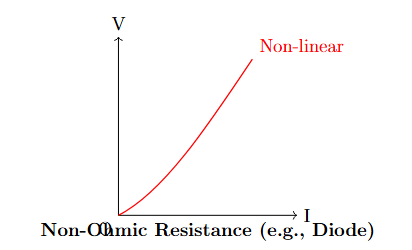
where is the voltage, is the current, and is the resistance. In ohmic materials, the resistance remains constant regardless of changes in the applied voltage or current. The graph of voltage versus current for an ohmic material is a straight line, indicating a constant resistance. For example, metals like copper and aluminum are ohmic resistors, as they maintain a linear relationship between voltage and current. The key point is that for ohmic resistors, the resistance does not change with temperature or voltage, as long as the material remains within its linear region. In other words, if we apply a higher voltage to an ohmic material, the current will increase proportionally, and the ratio of voltage to current will stay the same. - **Non-Ohmic Resistance:** Non-ohmic resistance refers to the resistance shown by materials that do not obey Ohm’s Law. In these materials, the relationship between the voltage and the current is not linear, and the resistance changes with varying voltage or current. Non-ohmic materials exhibit a variable resistance that depends on factors such as temperature, the direction of current, or the applied voltage. For example, semiconductors like diodes or light bulbs show non-ohmic behavior. A diode, for instance, has a very small current when the voltage is below a certain threshold (reverse or forward bias), but once the threshold is exceeded, the current increases exponentially with voltage, which results in a nonlinear - characteristic. The graph of voltage vs current for a non-ohmic resistor is not a straight line but a curve, reflecting that the resistance is changing as voltage and current vary. Other examples of non-ohmic resistances include light bulbs, where the filament's resistance increases as the temperature rises due to an increase in current. Dynamic Resistance: Dynamic resistance, also called incremental resistance, is the resistance of a non-ohmic component at a particular point on its current-voltage curve. It is defined as the ratio of the change in voltage ( ) to the change in current ( ) for small variations around a particular operating point on the curve. Mathematically, dynamic resistance is expressed as:
This expression allows us to find the resistance at a specific point on the curve where the voltage and current are not constant. For instance, in a diode, the dynamic resistance changes depending on the voltage and current applied. At very small voltages (below the threshold), the dynamic resistance is very high, but after the threshold voltage is surpassed, the resistance drops significantly, and current increases more rapidly. Dynamic resistance is particularly useful for analyzing devices where the current-voltage relationship is nonlinear, such as in diodes or transistors. In contrast to static resistance, which is a fixed value in ohmic materials, dynamic resistance provides an instantaneous measure of how the component behaves under varying conditions.
29
PYQ 2023
medium
physicsID: up-board
Two ideal batteries of same emf (E₁ = E₂) and same internal resistance (r₁ = r₂) are connected in parallel. Their equivalent emf is E and internal resistance is r. The correct option is
1
the equivalent emf E is E = E₁ - E₂ and r = r₁ - r₂
2
the equivalent emf E is E = E₁ + E₂ and r = r₁ + r₂
3
the equivalent emf E is E = E₁ = E₂ but r
4
the equivalent emf E is E = E₁ but r>r₁, r'>r₂
Official Solution
Correct Option: (3)
Step 1: Parallel Connection of Batteries. When two ideal batteries with the same emf and internal resistance are connected in parallel, their combined emf remains the same. The internal resistances, however, combine in parallel, so the resultant internal resistance is less than each individual internal resistance.
Step 2: Analysis of options. - ( The difference of emf is not correct for parallel batteries.
- ( The sum of emf is incorrect for parallel batteries.
- ( Correct: the combined emf remains the same, but the equivalent internal resistance is less than each individual internal resistance.
- ( Incorrect, the internal resistance will decrease in parallel, not increase.
Step 3: Conclusion. Thus, the correct answer is ( the equivalent emf E is E₁ = E₂ but r
30
PYQ 2025
medium
physicsID: up-board
Define drift velocity and mobility of electrons in a metallic conductor. The length of a conducting rod is 1 m and the potential difference between its ends is 4 volt. Electron density in the conductor is and its resistivity is -m. Calculate the drift velocity of the electrons in the metal.
Official Solution
Correct Option: (1)
Drift Velocity and Mobility of Electrons:
- Drift velocity ( ) is the average velocity of electrons in a conducting material under the influence of an electric field.
- Mobility ( ) refers to the speed of an electron in a material when exposed to an electric field. It is given by the relation: Where is the drift velocity, is the mobility, and is the electric field. For a conductor, the drift velocity can also be related to the current, electron density, and cross-sectional area. Step 1: Calculate the Electric Field
The electric field in the conductor is given by: Where is the potential difference and is the length of the conductor. Step 2: Apply Ohm's Law
The current in the conductor is related to the resistivity ( ), the current density ( ), and the electric field ( ) by: Where is the electrical conductivity and is the resistivity of the material. The current density is also related to the drift velocity and the electron density by: Where: - is the electron density ( ), - is the electron charge ( ),
- is the drift velocity. Equating both expressions for : Step 3: Calculate the Drift Velocity
Rearranging the equation to solve for : Substitute the known values:
- ,
- ,
- ,
- -m. Thus, the drift velocity of the electrons is:
31
PYQ 2025
medium
physicsID: up-board
Find the currents in the resistors and in the network shown in figure, also find charge on the capacitor : \includegraphics[width=0.5\linewidth]{2.png}
Official Solution
Correct Option: (1)
Step 1: Understanding the Concept (Steady State in DC Circuit):
This is a DC circuit containing a capacitor. When a DC voltage is applied, the capacitor charges up. After a long time, it becomes fully charged and its acts as an open circuit, meaning no current can flow through the branch containing the capacitor. This is called the steady state.
Step 2: Circuit Analysis at Steady State:
\begin{enumerate} \item Current in the 10 resistor: At steady state, the capacitor is fully charged and blocks the flow of DC current. Therefore, the current in the middle branch, which contains the resistor, becomes zero. \item Current in the 2 resistor: Since no current flows through the middle branch, the circuit simplifies to a single series loop consisting of the V battery, the resistor, and the resistor. The total resistance in this loop is: Using Ohm's law, the current flowing through this loop is: This is the current flowing through both the and resistors. \item Charge on the Capacitor: To find the charge on the capacitor, we first need to find the potential difference (voltage) across it. The capacitor and the 10 resistor are connected in parallel with the resistor (based on the common interpretation of this circuit's drawing). Therefore, the voltage across the capacitor branch is the same as the voltage across the resistor. The voltage across the resistor can be calculated using Ohm's law, with the current we found in the previous step: So, the voltage across the capacitor is V. Note that because the current through the 10 resistor is zero, there is no voltage drop across it, so the full 1.6 V appears across the capacitor plates. The charge on the capacitor is given by :
\end{enumerate}
Step 3: Final Answer:
\begin{itemize} \item Current in the resistor = 0.2 A. \item Current in the resistor = 0 A. \item Charge on the capacitor = 16 C.
\end{itemize}
32
PYQ 2025
medium
physicsID: up-board
Write Kirchhoff's laws related to electric circuit by drawing suitable circuit diagram.
Official Solution
Correct Option: (1)
Step 1: Understanding the Concept:
Kirchhoff's laws are two rules that deal with the conservation of charge and energy within electrical circuits. They provide a systematic way to analyze complex circuits that cannot be simplified into simple series or parallel combinations.
Step 2: Detailed Explanation: 1. Kirchhoff's First Law (Junction Rule or Kirchhoff's Current Law - KCL)
\begin{itemize} \item Statement: The algebraic sum of all electric currents meeting at any junction (or node) in a circuit is zero. In other words, the total current entering a junction must equal the total current leaving that junction. \item Principle: This law is based on the law of conservation of charge. Charge cannot accumulate at a junction. \item Equation: \item Circuit Diagram: Consider a junction 'A' where currents and are entering, and currents and are leaving. \begin{center} \begin{circuitikz}[american currents] \draw (0,0) node[circ] (A) {} node[above left] {A}; \draw (A) -- ++(-1,1) to[short, i<= ] ++(-1,0); \draw (A) -- ++(-1,-1) to[short, i<= ] ++(-1,0); \draw (A) -- ++(1,1) to[short, i>= ] ++(1,0); \draw (A) -- ++(1,-1) to[short, i>= ] ++(1,0); \end{circuitikz} \end{center} According to KCL, if we consider incoming currents as positive and outgoing currents as negative:
or,
\end{itemize}
\vspace{0.3cm}
2. Kirchhoff's Second Law (Loop Rule or Kirchhoff's Voltage Law - KVL)
\begin{itemize} \item Statement: The algebraic sum of the changes in electric potential (voltage) encountered in a complete traversal of any closed loop in a circuit is zero. \item Principle: This law is based on the law of conservation of energy. The net energy gained by a charge after moving around a closed loop must be zero. \item Equation: \item Circuit Diagram: Consider a simple closed loop containing a voltage source (EMF ) and two resistors and , with a current flowing through them. \begin{center} \begin{circuitikz}[american voltages] \draw (0,0) to[battery, l= ] (0,3) to[R, l= ] (3,3) to[R, l= ] (3,0) to[short] (0,0); \node at (1.5,1.5) [rotate=-90] {\huge }; \node at (2.1,1.5) { }; \end{circuitikz} \end{center} To apply KVL, we choose a direction (e.g., clockwise) and sum the potential changes: - Traversing the battery from negative to positive terminal: Potential gain of . - Traversing resistor in the direction of current: Potential drop of . - Traversing resistor in the direction of current: Potential drop of . The sum of these potential changes is zero:
\end{itemize}
Step 3: Final Answer:
Kirchhoff's two laws are the Junction Rule, which states that the sum of currents at a junction is zero ( ), and the Loop Rule, which states that the sum of potential differences around any closed loop is zero ( ).
33
PYQ 2025
medium
physicsID: up-board
Write the unit of specific resistance.
Official Solution
Correct Option: (1)
Step 1: Understanding the Concept:
Specific resistance, also known as resistivity, is an intrinsic property of a material that quantifies how strongly it resists the flow of electric current. It is denoted by the Greek letter (rho).
Step 2: Key Formula or Approach:
The resistance of a uniform conductor is related to its resistivity ( ), length ( ), and cross-sectional area ( ) by the formula:
We can rearrange this formula to solve for resistivity :
Step 3: Detailed Explanation:
To find the unit of resistivity, we can substitute the SI units for the quantities on the right side of the rearranged formula:
\begin{itemize} \item The unit of resistance ( ) is the ohm ( ). \item The unit of area ( ) is the square meter ( ). \item The unit of length ( ) is the meter ( ).
\end{itemize}
Substituting these units into the equation for :
Simplifying the expression, we get:
Step 4: Final Answer:
The SI unit of specific resistance (resistivity) is the ohm-meter ( ).
34
PYQ 2025
medium
physicsID: up-board
Two cells are of emf's and and their internal resistances are and respectively. They are joined in parallel to each other. Obtain the formula for the equivalent emf of this combination of cells.
Official Solution
Correct Option: (1)
When two cells with different electromotive forces (emfs) and internal resistances are connected in parallel, the equivalent emf and the equivalent internal resistance can be found using the following approach: Step 1: Calculate the equivalent internal resistance.
The two internal resistances and are in parallel, so the total internal resistance is given by: Therefore, the equivalent internal resistance is: Step 2: Calculate the equivalent emf.
The equivalent emf of two cells in parallel is given by the formula: This formula takes into account both the emfs and the internal resistances of the two cells. The equivalent emf is a weighted average of the two emfs, where the internal resistances act as the weights. Thus, the formula for the equivalent emf of the combination of cells is:
35
PYQ 2025
medium
physicsID: up-board
What is the first law of Kirchhoff of the electrical circuit? Find out the potential difference between the ends of 2 resistor with the help of Kirchhoff's law. See the figure: \includegraphics[width=0.5\linewidth]{image3.png}
Official Solution
Correct Option: (1)
Kirchhoff's First Law (or Junction Law) states that the algebraic sum of currents entering a junction is equal to the algebraic sum of currents leaving the junction. Mathematically, this can be written as: In the given circuit, we have two batteries and resistors. The resistances and voltages are given as: - , , ,
- , . We need to find the potential difference across the 2 resistor . To solve this using Kirchhoff's law, we first assign current directions (say , , and for different parts of the circuit) and write the equations for the loops in the circuit. Step 1: Apply Kirchhoff's Voltage Law (KVL) to Loop 1 (containing , , and ): Substitute the values: Step 2: Apply Kirchhoff's Voltage Law (KVL) to Loop 2 (containing , , and ): Substitute the values: Step 3: Apply Kirchhoff's Current Law (KCL) at the junction (where , , and meet): Step 4: Solve the system of equations. From Equations 1, 2, and 3, solve for the currents , , and . The potential difference across the resistor is . Calculation: Using the junction equation and solving for currents, we find the potential difference across .
36
PYQ 2025
medium
physicsID: up-board
Establish the relation between the resistances of arms of wheatstone bridge in balance conditions. OR The ratio of lengths and masses of three wires of same metal are 3 : 2 : 1 and 1 : 2 : 3 respectively. Find the ratio of resistances of those wires.}
Official Solution
Correct Option: (1)
Part I: Wheatstone Bridge Step 1: Principle and Diagram: A Wheatstone bridge is an electrical circuit used to measure an unknown electrical resistance by balancing two legs of a bridge circuit. The circuit consists of four resistors P, Q, R, and S arranged in a quadrilateral shape. A galvanometer G is connected between two opposite junctions, and a voltage source is connected to the other two junctions. Step 2: Balanced Condition and Derivation: The bridge is said to be balanced when no current flows through the galvanometer ( ). This occurs when the potential at point B is equal to the potential at point D ( ). Let the current from the source split at A into (through P) and (through R). When the bridge is balanced ( ), the current also flows through Q, and the current also flows through S. Since , the potential drop across P must be equal to the potential drop across R. Similarly, the potential drop across Q must be equal to the potential drop across S. Dividing equation (1) by equation (2), we get: This is the required relation for a balanced Wheatstone bridge. Part II: OR Question Step 1: Key Formulas: The resistance R of a wire is given by , where is the resistivity, L is the length, and A is the cross-sectional area. The mass m of a wire is given by . Step 2: Deriving the Resistance Ratio Formula: From the mass formula, we can express the area A as . Substituting this into the resistance formula: Since the three wires are made of the "same metal", their resistivity ( ) and density ( ) are the same. Therefore, the resistance is proportional to . So, the ratio of their resistances will be: Step 3: Calculation: We are given the ratios: Ratio of lengths, Ratio of masses, Substituting these ratios into our derived proportion: To express this ratio in integers, we multiply all parts by 3: Step 4: Final Answer: The ratio of the resistances of the three wires is 27 : 6 : 1.
37
PYQ 2025
medium
physicsID: up-board
Draw the graph between Voltage (V) and Current (I) for ohmic and non-ohmic resistances.
Official Solution
Correct Option: (1)
Step 1: Understanding the Concept: Ohmic resistances (or conductors) are those that obey Ohm's Law, which states that the current (I) through a conductor is directly proportional to the voltage (V) across it, provided the temperature and other physical conditions remain unchanged ( ). Non-ohmic resistances are those that do not obey Ohm's Law. Their V-I relationship is not linear. Step 2: V-I Graph for Ohmic Resistance: According to Ohm's Law, . If R is constant, this is the equation of a straight line passing through the origin, with the slope equal to the resistance R ( ). Step 3: V-I Graph for Non-Ohmic Resistance: For non-ohmic devices, the resistance is not constant but changes with voltage or current. The V-I graph is a curve, not a straight line. Examples include semiconductor diodes, transistors, and thermistors. Graph Explanation: Ohmic: A straight line through the origin indicates a constant ratio of V to I, meaning constant resistance. Non-Ohmic: The curve shows that the ratio of V to I (the resistance) is not constant. The slope of the tangent at any point on the curve gives the dynamic resistance.
38
PYQ 2025
medium
physicsID: up-board
Derive the formula for electric field due to a uniformly charged straight wire of infinite length using Gauss's law.
Official Solution
Correct Option: (1)
Step 1: Understanding the Concept and Choosing a Gaussian Surface:
We want to find the electric field ( ) at a distance from an infinitely long straight wire with a uniform linear charge density (charge per unit length). Gauss's law is effective for symmetric charge distributions. Due to the cylindrical symmetry of the infinite wire, the electric field must be directed radially outwards (for ) and its magnitude can only depend on the radial distance . We choose a cylindrical Gaussian surface of radius and length , coaxial with the wire. Step 2: Applying Gauss's Law:
Gauss's law states that the total electric flux ( ) through a closed surface is equal to the net charge enclosed ( ) divided by the permittivity of free space ( ).
The total flux through our cylindrical surface can be split into the flux through the two flat end caps (top and bottom) and the flux through the curved side wall.
Step 3: Calculating the Electric Flux: Flux through the end caps: On the top and bottom circular surfaces, the electric field vector is radial and perpendicular to the wire, while the area vector is directed along the axis of the cylinder (upwards for the top cap, downwards for the bottom). Thus, is perpendicular to , and the angle between them is 90 . So, the flux through the top and bottom caps is zero. Flux through the curved surface: On the curved side wall, the electric field vector is always parallel to the area vector (both point radially outwards). The angle between them is 0 . Since the magnitude of the electric field E is constant at a fixed distance r from the wire, we can take it out of the integral. Step 4: Calculating the Enclosed Charge and Final Formula:
The charge enclosed by the Gaussian surface of length is the linear charge density multiplied by the length .
Now, we substitute the flux and enclosed charge back into Gauss's law:
The length cancels out from both sides, which is expected as the wire is infinitely long.
This is the formula for the electric field due to an infinitely long charged wire. The field is inversely proportional to the distance from the wire.
39
PYQ 2025
medium
physicsID: up-board
A conductor has positive charge of coulomb. Find how much electrons are in deficit/excess on the conductor.
Official Solution
Correct Option: (1)
Step 1: Understanding the Concept:
The charge on any object is an integer multiple of the elementary charge (the charge of a single electron). This is the principle of quantization of charge. A positive charge on a conductor indicates a removal of electrons, leading to a deficit. Step 2: Key Formula or Approach:
The formula for quantization of charge is:
where: Q is the total charge on the object.
n is the number of electrons in excess or deficit (must be an integer).
e is the magnitude of the elementary charge, C. We need to solve for n. Step 3: Detailed Explanation:
We are given: Total charge C.
Elementary charge C. Rearranging the formula to solve for n:
Substituting the values:
Since the charge Q is positive, it means that electrons (which are negatively charged) have been removed from the conductor. Therefore, there is a deficit of 15 electrons. Step 4: Final Answer:
The conductor has a deficit of 15 electrons.
40
PYQ 2025
medium
physicsID: up-board
Electron in the hydrogen atom is moving round the nucleus with cycle per second. What will be the value of current at a point on circular path ?
Official Solution
Correct Option: (1)
Step 1: Understanding the Concept:
An electron revolving in a circular orbit constitutes an electric current. The current is defined as the rate of flow of charge. For a revolving electron, the current at any point on the orbit is the total charge that passes that point per unit time. Step 2: Key Formula or Approach:
The electric current (I) is given by:
In this case, Q is the charge of the electron (e), and the time taken for one revolution is the time period (T). So, .
The frequency (f) is the number of cycles per second, which is the reciprocal of the time period ( ).
Therefore, the formula can be written as:
Step 3: Detailed Explanation:
We are given: Frequency of revolution cycles/second (or Hz).
The charge of an electron C. Now, we can calculate the current using the formula :
This can also be expressed as:
Step 4: Final Answer:
The value of the current at a point on the circular path is A or 0.96 mA.
41
PYQ 2025
medium
physicsID: up-board
Define electromotive force of a cell.
Official Solution
Correct Option: (1)
Core definition.
The electromotive force (emf) of a cell is the work done by the cell's non-electrostatic (chemical) forces in moving unit positive charge once around the entire circuit (including the cell's interior).
Mathematically,
where is the work performed by the cell on charge . Its SI unit is the volt (V) . Physical interpretation.
Inside the cell, chemical reactions separate charges against the internal electric field. This "source" work per unit charge is the emf. When no current flows (open circuit), the terminal potential difference equals . Circuit relation (with internal resistance).
If the cell has internal resistance and supplies a current to an external circuit of resistance , then the terminal voltage is
Thus represents the "total available push" per unit charge; a portion is lost inside the cell. Integral form (general).
More generally, for any source,
the line integral of the non-electrostatic force per unit charge around the loop (chemical, mechanical, photovoltaic, etc.). Key properties. is independent of load in the ideal (no internal resistance) case; real cells show a drop in terminal voltage under load due to .
Dimensions: (volt).
42
PYQ 2025
medium
physicsID: up-board
To measure potential difference from a galvanometer, we connect in it:
1
a high resistance in series
2
a low resistance in parallel
3
a high resistance in parallel
4
a low resistance in series
Official Solution
Correct Option: (1)
Step 1 (What a galvanometer does). A moving–coil galvanometer is a current detector with internal resistance and full–scale current . By itself it measures small currents, not voltage. Step 2 (Convert to voltmeter). To measure a potential difference without disturbing the circuit, the instrument must draw very little current. We therefore add a large series (multiplier) resistance : .
Choosing so that at full–scale makes a voltmeter whose internal resistance is very large, hence negligible loading of the circuit. Step 3 (Why others are wrong). A low parallel resistance (shunt) is for ammeters, not voltmeters; a high parallel resistance diverts current unpredictably; a low series resistance draws too much current and loads the circuit.
We must connect a high resistance in series.
43
PYQ 2025
medium
physicsID: up-board
The unit of permittivity of vacuum is :
1
Newton m /coulomb
2
coulomb /Newton m
3
Newton/coulomb
4
Newton volt/m
Official Solution
Correct Option: (2)
Step 1: Understanding the Concept:
The permittivity of vacuum, denoted by , is a physical constant that represents the capability of a vacuum to permit electric field lines. Its unit can be derived from any equation where it appears, most commonly Coulomb's Law. Step 2: Key Formula or Approach:
Coulomb's Law for the electrostatic force (F) between two point charges (q and q ) separated by a distance (r) is:
We can rearrange this formula to solve for and then find its units. Step 3: Detailed Explanation:
Rearranging Coulomb's Law to solve for :
Now, let's substitute the SI units for each quantity (the constant is dimensionless): Force (F): Newton (N)
Charge (q , q ): Coulomb (C)
Distance (r): meter (m) Substituting these into the rearranged formula:
This can be written as coulomb /Newton m . Step 4: Final Answer:
The unit of permittivity of vacuum is coulomb /Newton m .
44
PYQ 2025
medium
physicsID: up-board
Electric field is applied across a metallic wire of length and area of cross-section . Obtain the formula of the relationship between the drift velocity ( ) of free electrons of the conductor and electric field in vector form.
Official Solution
Correct Option: (1)
When an electric field is applied across a metallic wire, the free electrons experience a force that causes them to move in the direction opposite to the electric field, resulting in a drift velocity . The relationship between the drift velocity and the electric field can be derived using the following steps: Step 1: Force on an electron due to electric field.
The force on an electron of charge due to the electric field is given by: Where:
- is the force on the electron,
- is the charge of the electron ( ),
- is the electric field. Step 2: Acceleration of an electron.
From Newton's second law, the acceleration of the electron is given by: Where:
- is the mass of the electron. Step 3: Drift velocity.
The drift velocity is the average velocity that the electron acquires due to the electric field. This velocity is reached after a characteristic time called the relaxation time , which is the average time between collisions of the electron with the atoms in the wire. The drift velocity is related to the acceleration by: Thus, the drift velocity of the electrons is given by: This equation gives the relationship between the drift velocity , the electric field , and the properties of the electron (charge and mass).
45
PYQ 2025
medium
physicsID: up-board
How is a galvanometer converted into a voltmeter?
Official Solution
Correct Option: (1)
A galvanometer can be converted into a voltmeter by connecting a high resistance in series with it. This series resistance is chosen such that it allows only a small current to flow through the galvanometer when a high potential difference is applied. The total resistance of the voltmeter is then the sum of the resistance of the galvanometer and the series resistance: This modification ensures that the voltmeter can measure high voltages without damaging the galvanometer or causing excessive current flow. The full-scale deflection of the galvanometer will correspond to the full-scale voltage of the voltmeter, which can be calibrated accordingly.
46
PYQ 2025
medium
physicsID: up-board
The correct relationship of mobility of charge carrier with drift velocity and electric field , is:
1
2
3
4
Official Solution
Correct Option: (1)
The mobility of a charge carrier is defined as the ratio of its drift velocity to the applied electric field . Mathematically, this is expressed as: Where:
- is the drift velocity of the charge carrier,
- is the electric field applied. Mobility is a measure of how quickly a charge carrier can move through a medium under the influence of an electric field. Therefore, the correct relationship is , which makes option (A) the correct answer. Hence, the correct answer is option (A) .
47
PYQ 2025
medium
physicsID: up-board
With the help of the given circuit, find out the total resistance of the circuit and the current flowing through the cell. \includegraphics[width=0.5\linewidth]{image4.png}
Official Solution
Correct Option: (1)
Given the circuit, we need to find out the total resistance and the current flowing through the cell. The circuit consists of resistors in both series and parallel combinations. 1. Total Resistance Calculation: - First, combine the resistors in parallel. The 500 and 750 resistors are in parallel, and the formula for the total resistance in parallel is: Simplifying this: 2. Total Resistance of the Circuit: - Now, this equivalent resistance (300 ) is in series with the 1000 resistor. The total resistance in series is simply the sum of the resistances: 3. Current Calculation: - Using Ohm's Law, , we can calculate the current flowing through the circuit. The given voltage is 4.75 V, and the total resistance is 1300 : Thus, the total resistance of the circuit is 1300 , and the current flowing through the cell is approximately 3.65 mA.
48
PYQ 2025
medium
physicsID: up-board
On connecting a cell of e.m.f. 0.5 volt with an external resistance of 1.9 , the current flowing is 0.75 A. The internal resistance of the cell is:
1
0.5 ohm
2
0.2 ohm
3
0.1 ohm
4
0.6 ohm
Official Solution
Correct Option: (2)
We can use Ohm's Law to calculate the internal resistance of the cell. The total voltage in the circuit is given by the e.m.f. of the cell, and the total resistance in the circuit is the sum of the internal resistance and the external resistance . The formula we use is: where:
- e.m.f. = 0.5 V,
- = 0.75 A,
- = 1.9 ,
- is the internal resistance of the cell. Substitute the values into the formula: Now, solve for : Now, calculate : Thus, the internal resistance of the cell is approximately 0.2 ohms.
49
PYQ 2025
medium
physicsID: up-board
Resistivity of a conducting wire depends on:
1
the length of the wire
2
the resistance of the wire
3
the material of the wire
4
the thickness of the wire
Official Solution
Correct Option: (3)
Resistivity ( ) is a property of the material itself and does not depend on the shape or size of the wire. It is determined by the material through which the current flows. The formula for resistivity is:
where:
- is the resistance,
- is the resistivity,
- is the length of the wire, D
- is the cross-sectional area of the wire. Thus, resistivity depends on the material, and it does not change with the length or thickness of the wire.
50
PYQ 2025
easy
physicsID: up-board
A resistance wire is bent into a shape of a circle. What will be the effective resistance between the ends of its diameter?
Official Solution
Correct Option: (1)
51
PYQ 2025
medium
physicsID: up-board
Write the Kirchhoff's law of voltage and current.
Official Solution
Correct Option: (1)
Gustav Kirchhoff formulated two fundamental laws that are essential for analyzing complex electrical circuits. 1. Kirchhoff's First Law (Kirchhoff's Current Law - KCL or the Junction Rule):
\begin{itemize} \item Statement: The algebraic sum of the electric currents meeting at any junction (or node) in an electrical circuit is zero. \item Mathematical Form: \item Explanation: This law is a direct consequence of the law of conservation of electric charge. Charge cannot be created, destroyed, or accumulated at a junction. Therefore, the total rate at which charge enters a junction must be equal to the total rate at which charge leaves it. \item Sign Convention: Currents entering a junction are typically taken as positive, while currents leaving the junction are taken as negative (or vice versa, as long as the convention is consistent).
\end{itemize} 2. Kirchhoff's Second Law (Kirchhoff's Voltage Law - KVL or the Loop Rule):
\begin{itemize} \item Statement: The algebraic sum of the changes in potential (or voltage drops and EMFs) around any closed loop or mesh in an electrical circuit is zero. \item Mathematical Form: \item Explanation: This law is based on the law of conservation of energy. The electric force is a conservative force. This means that if an electric charge is moved around any closed path and returns to its starting point, the net work done on it is zero. Consequently, its net change in potential energy, and therefore electric potential, is also zero. \item Sign Convention: When traversing a loop, the potential difference across a resistor is taken as negative if moving in the direction of the current and positive if moving against it. The EMF of a source is taken as positive if moving from the negative to the positive terminal and negative if moving from positive to negative.
\end{itemize}
52
PYQ 2025
medium
physicsID: up-board
The ratio of diameters of two copper wires of same length is 2 : 1. Compare their resistances.
Official Solution
Correct Option: (1)
Step 1: Understanding the Concept:
The electrical resistance ( ) of a conductor depends on its intrinsic property (resistivity, ), its length ( ), and its cross-sectional area ( ). Since the problem specifies two copper wires of the same length, their resistivity and length are identical. Therefore, the difference in their resistance will solely depend on their cross-sectional areas, which are determined by their diameters.
Step 2: Key Formula or Approach:
The formula for the resistance of a wire is:
The cross-sectional area of a wire with diameter is circular, so its area is:
Substituting the area into the resistance formula shows that resistance is inversely proportional to the square of the diameter:
Step 3: Detailed Explanation:
Let the two wires be designated as Wire 1 and Wire 2.
We are given the following information:
\begin{itemize} \item Same material (copper): \item Same length: \item Ratio of diameters:
\end{itemize}
We want to find the ratio of their resistances, .
Using the resistance formula for both wires:
Since and are the same, they cancel out, leaving:
Now, substitute the formula for area in terms of diameter:
We are given , which means .
Substituting this value into our ratio:
Step 4: Final Answer:
The ratio of the resistances is 1 : 4. This means the thicker wire ( ) has one-fourth the resistance of the thinner wire ( ).