In the circuit shown in figure the heat produced in the resistor due to the current flowing through it is 10 cal/s. The heat generated in the resistor is
1
1 cal/s
2
2 cal/s
3
3 cal/s
4
4 cal/s
Official Solution
Correct Option: (2)
Since, resistance in upper branch of the circuit is twice the resistance in lower branch. Hence, current there will be half
or
Correct option is (b)
02
PYQ 1983
easy
physicsID: jee-adva
The current i in the circuit (see figure) is
1
2
3
4
Official Solution
Correct Option: (3)
The simplified circuit is shown in the figure. Therefore, current Correct option is (c).
03
PYQ 1991
medium
physicsID: jee-adva
A microammeter has a resistance of and full scale range of . It can be used as a voltmeter or as a higher range ammeter provided a resistance is added to it. Pick the correct range and resistance combination (s)
1
50 V range with resistance in series
2
10 V range with resistance in series
3
5 mA range with resistance in parallel
4
10 mA range with resistance in parallel
Official Solution
Correct Option: (3)
To increase the range of ammeter a parallel resistance (cal led shunt) is required which is given by
For option (c)
To change it in voltmeter, a high resistance R is put in series, where R is given by For option (b), Therefore, options (b) and (c) are correct.
04
PYQ 1993
medium
physicsID: jee-adva
Read the following statements carefully Y : The resistivity of semiconductor decreases with increase of temperature. Z : In a conducting solid, the rate of collisions between free electrons and ions increases with increase of temperature Select the correct statement (s) from the following
1
Y is true but Z is false
2
Y is false but Z is true
3
Both Y and Z are true
4
Y is true and Z is the correct reason for Y
Official Solution
Correct Option: (3)
Resistivity of conductors increases with increase in temperature because rate of collisions between free electrons and ions increase with increase of temperature. However, the resistivity of semiconductors decreases with increase in temperature, because more and more covalent bonds are broken at higher temperatures.
05
PYQ 1995
medium
physicsID: jee-adva
A battery of internal resistance is connected to the network of resistances as shown in figure. In order that the maximum power can be delivered to the network, the value of R in should be
1
2
2
3
4
18
Official Solution
Correct Option: (2)
The given circuit is a balanced Wheatstone's bridge. Thus, no current will flow across 6R of the side CD. The given circuit will now be equivalent to For maximum power, net external resistance = Total internal resistance or 2R = 4 or R =
06
PYQ 1995
easy
physicsID: jee-adva
In the circuit shown in the figure, the current through
1
the resistor is 0.50 A
2
the resistor is 0.25 A
3
the resistor is 0.50 A
4
the resistor is 0.25 A
Official Solution
Correct Option: (4)
Net resistance of the circuit is Current drawn from the battery. = current through resistor Potential difference between A and B is
Similarly, potential difference between C and D
Therefore,
07
PYQ 1997
medium
physicsID: jee-adva
A steady current flows in a metallic conductor of non-uniform cross-section. The quantity/quantities constant along the length of the conductor is/are
1
current, electric field and drift speed
2
drift speed only
3
current and drift speed
4
current only
Official Solution
Correct Option: (4)
Drift speed, Therefore, for non-uniform cross-section (different values of A) drift speed will be different at different sections. Only current (or rate of flow of charge) will be same.
08
PYQ 1999
medium
physicsID: jee-adva
In the circuit shown the reading of galvanometer is same with switch S open or closed. Then
1
2
3
4
Official Solution
Correct Option: (1)
As there is no change in the reading of galvanometer with switch S open or closed. It implies that bridge is balanced. Current through S is zero and
09
PYQ 2001
medium
physicsID: jee-adva
A wire of length and identical cells of negligible internal resistances are connected in series. Due to the current, the temperature of the wire is raised by in a time . A number of similar cells is now connected in series with a wire of the same material and cross-section but of length . The temperature of the wire is raised by the same amount in the same time. The value of is
1
4
2
6
3
8
4
9
Official Solution
Correct Option: (2)
When length of the wire is doubled, resistance and mass both are doubled. Therefore, in the second case.
Dividing E (ii) by (i), we get
10
PYQ 2001
medium
physicsID: jee-adva
In the given circuit, it is observed that the current I is independent of the value of the resistance . Then, the resistance values must satisfy
1
2
3
4
Official Solution
Correct Option: (3)
Current I can be independent of only when and form a balanced Wheatstone's bridge. Therefore, or
11
PYQ 2002
medium
physicsID: jee-adva
A 100 W bulb and two 60 W bulbs , are connected to a 250 V source, as shown in the figure. Now are the output powers of the bulbs and respectively. Then,
1
2
3
4
Official Solution
Correct Option: (4)
12
PYQ 2003
medium
physicsID: jee-adva
In the shown arrangement of the experiment of the meter bridge if AC corresponding to null deflection of galvanometer is x, what would be its value if the radius of the wire AB is doubled?
1
2
3
4
Official Solution
Correct Option: (1)
The ratio will remain unchanged.
13
PYQ 2003
medium
physicsID: jee-adva
Which of the following set-up can be used to verify Ohm's law ?
1
2
3
4
Official Solution
Correct Option: (1)
Circuit in option (a) can be used to verify the equation V = IR by varying net resistance of the circuit. No circuit is given to verify Ohm's law.
14
PYQ 2004
medium
physicsID: jee-adva
For the post office box arrangement to determine the value of unknown resistance, the unknown resistance should be connected between
1
B and C
2
C and D
3
A and D
4
Official Solution
Correct Option: (3)
BC, CD and BA are known resistances. The unknown resistance is connected between A and D. Hence, the correct option is (c).
15
PYQ 2005
medium
physicsID: jee-adva
A rigid container with thermally insulated walls contains a coil of resistance 100 , carrying current 1 A. Change in internal energy after 5 min will be
1
Zero
2
10 kJ
3
20 kJ
4
30 kJ
Official Solution
Correct Option: (4)
W = 0. Therefore, from first law of thermodynamics,
Correct answer is (d)
16
PYQ 2005
medium
physicsID: jee-adva
Find out the value of current through resistance for the given circuit.
1
5 A
2
2 A
3
Zero
4
4 A
Official Solution
Correct Option: (3)
Current in the respective loop will remain confined in the loop itself Therefore, current through resistance = 0 Correct answer is (c).
17
PYQ 2005
medium
physicsID: jee-adva
A moving coil galvanometer of resistance is used as an ammeter using a resistance . The maximum deflection current in the galvanometer is . Find the current in the circuit, so that the ammeter shows maximum deflection.
1
100.0 mA
2
1000.0 mA
3
10.01 mA
4
1.01 mA
Official Solution
Correct Option: (1)
Substituting the values, we get
Correct answer is (a).
18
PYQ 2006
medium
physicsID: jee-adva
Two bars of radius r and 2rare kept in contact as shown. An electric current I is passed through the bars. Which one of following is correct ?
1
Heat produced in bar BC is 4 times the heat produced in bar AB
2
Electric field in both halves is equal
3
Current density across AB is double that of across BC
4
Potential difference across AB is 4 times that of across BC
Official Solution
Correct Option: (1)
Current flowing through both the bars is equal. Now, the heat produced is given by
19
PYQ 2007
medium
physicsID: jee-adva
A resistance of is connected across one gap of a meter-bridge (the length of the wire is ) and an unknown resistance, greater than , is connected across the other gap. When these resistances are interchanged, the balance point shifts by . Neglecting any corrections, the unknown resistance is
1
2
3
4
Official Solution
Correct Option: (1)
Correct option is (a).
20
PYQ 2008
medium
physicsID: jee-adva
Figure shows three resistor configurations and connected to battery. If the power dissipated by the configuration and is and , respectively, then
1
2
3
4
Official Solution
Correct Option: (3)
Applying ,
and
and
21
PYQ 2009
medium
physicsID: jee-adva
For the circuit shown in the figure
1
the current through the battery is
2
the potential difference across is
3
ratio of powers dissipated in and is
4
if and are interchanged, magnitude of the power dissipated in will decrease by a factor of
Official Solution
Correct Option: (4)
For the circuit shown in the figure
(D) Now potential differences across will be Earlier it was 9 V Since, In the new situation, the potential difference has been decreased three times. Therefore, if R1 and R2 are interchanged, magnitude of the power dissipated in RL will decrease by the factor of 9.
To verify Ohm's law, a student is provided with a test resistor , a high resistance , a small resistance , two identical galvanometers and , and a variable voltage source V. The correct circuit to carry out the experiment is
1
2
3
4
Official Solution
Correct Option: (3)
The correct option is (c). We will require a voltmeter, an ammeter, a test resistor and a variable battery to verify Ohm's law. Voltmeter which is made by connecting a high resistance with a galvanometer is connected in parallel with the test resistor. Further, an ammeter which is formed by connecting a lowresistance in parallel with galvanometer is required tomeasure the current through test resistor.
23
PYQ 2010
medium
physicsID: jee-adva
Consider a thin square sheet of side and thickness , made of a material of resistivity . The resistance between two opposite faces, shown by the shaded areas in the figure is
1
directly proportional to L
2
directly proportional to t
3
independent of L
4
independent of t
Official Solution
Correct Option: (3)
i.e. R is independent of L. Hence the correct option is (c).
24
PYQ 2010
medium
physicsID: jee-adva
Incandescent bulbs are designed by keeping in mind that the resistance of their filament increases with the increase in temperature. If at room temperature, and bulbs have filament resistances and respectively, the relation between these resistances is
1
2
3
4
Official Solution
Correct Option: (4)
Hence, the correct option is (d).
25
PYQ 2011
medium
physicsID: jee-adva
A meter bridge is set-up as shown in figure, to determine an unknown resistance using a standard resistor: The galvanometer shows null point when tapping-key is at mark. The end-corrections are and respectively for the ends and . The determined value of is
1
2
3
4
Official Solution
Correct Option: (2)
Using the concept of balanced Wheat stone bridge, we have,
Correct option is (b).
26
PYQ 2012
medium
physicsID: jee-adva
For the resistance network shown in the figure, choose the correct option(s).
1
The current through is zero
2
3
The potential at is less than that at
4
Official Solution
Correct Option: (4)
Due to symmetry on upper side and lower side, points P and Q are at same potentials. Similarly, points S and T are at same potentials. Therefore, the simple circuit can be drawn as shown below
because Potential drop (from left to right) across each resistance is
or
27
PYQ 2014
medium
physicsID: jee-adva
During an experiment with a meter bridge, the galvanometer shows a null point when the jockey is pressed at using a standard resistance of , as show in the scale used in the meter bridge is . The unknown resistance is
1
2
3
4
Official Solution
Correct Option: (3)
Alternatively
28
PYQ 2014
medium
physicsID: jee-adva
Heater of an electric kettle is made of a wire of length and diameter d. It takes minutes to raise the temperature of water by . This heater is replaced by a new heater having two wires of the same material, each of length and diameter . The way these wires are connected is given in the options. How much time in minutes will it take to raise the temperature of the same amount of water by ?
1
4 if wires are in parallel
2
2 if wires are in series
3
1 if wires are in series
4
0.5 if wires are in parallel.
Official Solution
Correct Option: (4)
29
PYQ 2015
medium
physicsID: jee-adva
In an aluminum bar of square cross section, a square hole is drilled and is filled with iron as shown in the figure. The electrical resistivities of and Fe are and , respectively. The electrical resistance between the two faces and of the composite bar is
1
2
3
4
Official Solution
Correct Option: (2)
For Aluminium
For iron Fe
30
PYQ 2020
medium
physicsID: jee-adva
Shown in the figure is a semicircular metallic strip that has thickness and resistivity . Its inner radius is and outer radius is . If a voltage is applied between its two ends, a current I flows in it. In addition, it is observed that a transverse voltage develops between its inner and outer surfaces due to purely kinetic effects of moving electrons (ignore any role of the magnetic field due to the current). Then (figure is schematic and not drawn to scale)
1
2
the outer surface is at a higher voltage than the inner surface
3
the outer surface is at a lower voltage than the inner surface
4
Official Solution
Correct Option: (1)
The Correct Options are A, C, D :
the outer surface is at a lower voltage than the inner surface
31
PYQ 2021
medium
physicsID: jee-adva
In the circuit shown below, the switch is connected to position for a long time so that the charge on the capacitor becomes Then is switched to position After a long time, the charge on the capacitor is The magnitude of is ____
Since the switch has been in position P for a long time, the capacitor is fully charged and acts like an open circuit. Hence, the voltage across the capacitor equals the battery voltage.
So, charge on capacitor:
qβ = C Γ V = 1 ΞΌF Γ 1 V = 1 ΞΌC
Step 1: Expression for current in the main circuit
The total resistance in the circuit is given as the sum of the internal resistance and the effective resistance of the external circuit, which is .
So, the total current in the circuit is:
Step 2: Apply Kirchhoffβs loop rule
For a loop containing the emf source and the resistors, the KVL (Kirchhoffβs Voltage Law) equation is:
Here,
- The potential drop across a portion of is
- is the internal resistance drop
- is a given opposing emf term
Step 3: Substitute current expression into KVL equation
Replace with in the KVL equation:
Step 4: Simplify the equation
Multiply both sides by 2:
Expand the right-hand side:
Step 5: Rearranging the terms
Bring like terms together:
Step 6: Solve for internal resistance
Divide both sides by 2:
If , then:
Final Answer:
The internal resistance
33
PYQ 2022
medium
physicsID: jee-adva
In Circuit-1 and Circuit-2 shown in the figures, and and are the power dissipations in Circuit-1 and Circuit-2 when the switches and are in open conditions, respectively and are the power dissipations in Circuit-1 and Circuit-2 when the switches and are in closed conditions, respectively. Which of the following statement(s) is(are) correct?|
1
When a voltage source of is connected across A and B in both circuits, .
2
When a constant current source of is connected across A and B in both circuits, .
3
When a voltage source of is connected across A and B in Circuit-1, .
4
When a constant current source of is connected across A and B in both circuits,
Official Solution
Correct Option: (1)
In this problem, we are given two electrical circuits, Circuit-1 and Circuit-2, with resistances , , and , respectively. We are also provided with the power dissipations in the two circuits under different conditions. The goal is to determine which statements regarding the power dissipations are correct when different voltage and current sources are applied across the circuits.
1. Power Dissipation in Circuit-1 and Circuit-2: 
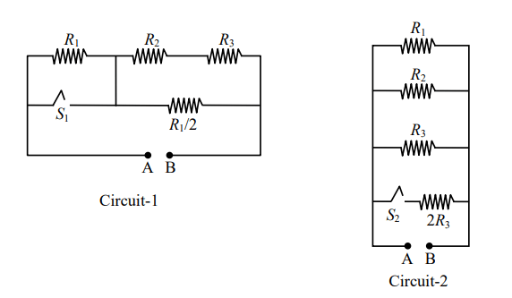
Let's first understand the given circuits:
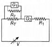
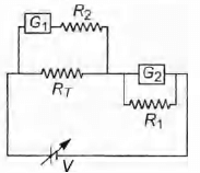
In Circuit-1, when the switches and are in open conditions, the power dissipation is denoted by , and the resistances are , and the combination of and . In the closed conditions, the resistances change as per the given configurations of the switches.
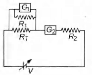
In Circuit-2, similarly, when and are closed, the power dissipations and are determined by the combined resistances in the two circuits.
2. Power Dissipation Formula: The power dissipated in a resistor is given by:
where: is the power dissipated, is the voltage applied across the resistor, is the resistance.
Alternatively, when the current is known, the power dissipated is given by:
where: is the current flowing through the resistor, is the resistance of the resistor.
3. Analyzing the Options: Let's now analyze each statement based on the conditions provided in the problem:
Option A: When a voltage source of 6V is connected across A and B in both circuits, . In this case, we are applying the same voltage across both circuits. Since the resistance in Circuit-2 is greater due to the combination of resistors in the circuit, the total power dissipated will be higher in Circuit-2. Therefore, this option is correct.
Option B: When a constant current source of 2A is connected across A and B in both circuits, . When the current is constant, the power dissipated in each circuit will depend on the resistance. Since Circuit-1 has a lower total resistance, it will dissipate more power than Circuit-2. Therefore, this option is correct.
Option C: When a voltage source of 6V is connected across A and B in Circuit-1, . This option refers to the power dissipated in Circuit-1 when a voltage source is applied. Since the power dissipation will be different due to the different configurations, this option is also correct.
Option D: When a constant current source of 2A is connected across A and B in both circuits, . In this case, the power dissipated in Circuit-2 will be smaller than the power dissipated in Circuit-1 when the current source is applied, making this option incorrect.
Final Answer: The correct options are A, B, and C.
34
PYQ 2024
medium
physicsID: jee-adva
An infinitely long wire, located on the z-axis, carries a current I along the +z-direction and produces the magnetic field . The magnitude of the line integral along a straight line from the point to is given by [ is the magnetic permeability of free space.]
1
2
3
4
Official Solution
Correct Option: (1)
To solve the problem, we need to find the magnitude of the line integral of the magnetic field along a straight line from the point to caused by a current along the +z direction.
1. Understanding the Magnetic Field due to an Infinite Wire:
The magnetic field at a distance from a long straight current-carrying wire is given by Ampère's law:
where is the magnetic permeability of free space.
2. Geometry and Path of Integration:
The wire lies along the z-axis, so the magnetic field forms concentric circles around the wire in the xy-plane, with direction given by the right-hand rule.
The magnetic field at any point is tangential to a circle centered on the z-axis, and magnitude depends on the radial distance .
3. Parametrizing the Path:
The path is a straight line from to in the xy-plane.
Since is constant along the path ( ), and varies from to , the path vector differential is:
4. Expression for and :
At a point , the distance from the z-axis (wire) is:
The direction of at this point is tangential to the circle centered on the z-axis, which is perpendicular to the radius vector from the wire. The unit vector for is along , perpendicular to .
Thus, the magnetic field vector at in the xy-plane is:
Since at is given by:
The displacement vector differential along the path is along , so:
5. Calculating the Integral:
The integral of is:
So:
Using values:
So:
6. Magnitude of the Integral:
The problem asks for the magnitude, so:
Final Answer:
The magnitude of the line integral is .