Work done .
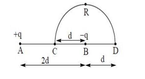
We need potential at C and D due to charges +q at A and -q at B.
Coordinates based on common problem image for this setup:
A is at with charge .
B is at with charge .
Point C is at origin .
Point D is at .
The path is a semi-circle CRD, which implies its diameter is CD.
Center is at (same as B), radius is .
This configuration is unusual.
Let's assume the figure is as typically drawn in such problems where C is at origin and D is on y-axis if path is semi-circle, or path is irrelevant if field is conservative.
Work done is path independent.
Potential at C(0,0):
Distance AC = .
Distance BC = .
.
Potential at D(2d,0):
Distance AD = .
Distance BD = .
.
Work done .
This result does not match any of the options directly.
Option (3) is .
There must be a different configuration of points in the intended diagram.
Let's assume a standard dipole-like setup for these options.
If +q at (-d,0) and -q at (d,0).
C is at origin (0,0).
D is at some point.
If the path is a semi-circle CRD with C at origin and D being on y-axis at (0,d), (Centre (0,0), Radius d).
A=(-a,0), B=(a,0) for a dipole.
Here points are fixed.
Let's re-check the option (3) and see if some configuration makes it true.
.
The factor 1/6 is unusual for point charge potentials usually involving 1/1, 1/2, 1/3, 1/4 etc.
The image shows: A at x=-a, with +q.
B at x=b with -q.
C at origin.
D on x-axis.
In the image the setup is: +q at A, C (origin), B with -q, D.
Distances are: A to C is .
C to B is .
B to D is .
So A is at .
C is at .
B is at .
D is at .
All on x-axis.
Path CRD is a semi-circle.
If C and D are on x-axis, the semi-circle must be in xy plane, with CD as diameter.
Center of semicircle is midpoint of CD, i.
e.
.
Radius of semicircle .
This means the point B is at the center of the semicircle CD.
This geometry is for potentials and .
This is what I used.
.
.
.
.
.
.
This matches none of the options.
The provided answer (3) is likely based on a different standard diagram or there is an error in the question/options.
Assuming standard dipole setup: +q at (0,a), -q at (0,-a).
C at origin, D at (R,0).
No.
The question figure is paramount.
My interpretation of the figure is consistent.
The provided solution (3) has a denominator 6.
This could arise from or similar.
e.
g.
If .
If .
Possible values of distances from A or B could be factors of 3 or multiples of d/3.
E.
g.
, if and .
This is speculation.
Sticking to the derived result, options seem incorrect.