In the circuit given below, if the bulb is to glow with maximum intensity, the value of 'R' is (neglect internal resistance of the cell)
1
2
3
4
Official Solution
Correct Option: (1)
The bulb is rated at 1. 5 V and 0. 45 W. To glow with maximum intensity, the voltage across the bulb should be 1. 5 V and the power dissipated should be 0. 45 W. We can find the resistance of the bulb using the power rating:
$ resistor in series with a parallel combination of resistor and the bulb with resistance . The total voltage of the cell is 6 V. For the voltage across the parallel combination (and hence across the bulb) to be 1. 5 V, the voltage drop across the 3 resistor must be V. Let the current through the 3 resistor be . Then, V, which gives A. This current is the total current flowing from the cell. It divides into two branches in the parallel combination: current through ( ) and current through the bulb ( ). The current through the bulb can be found using its power rating and voltage:
\) is . Since the voltage across is the same as the voltage across the bulb (parallel combination), which is 1. 5 V, we can find the value of using Ohm's law:
\) $ The value of required for the bulb to glow with maximum intensity is 1. 25 .
02
PYQ 2023
medium
physicsID: ap-eapce
The incorrect statement regarding the given circuit
1
current through 2 is 2A
2
current through 3 is 4A
3
potential at C is 12 V
4
potential at A is 10 V
Official Solution
Correct Option: (4)
Let's analyze the circuit using Kirchhoff's laws. Assume the potential at point C is . 
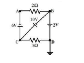
Applying Kirchhoff's Voltage Law (KVL) to the loop containing the 6V battery, 2 resistor, and the path from A to C:
(Equation 1)
where is the current through the 2 resistor, flowing from C to A. Applying KVL to the loop containing the 2V battery, 3 resistor, and the path from D to C:
(Equation 2)
where is the current through the 3 resistor, flowing from C to D. Applying KVL to the loop containing the 10V battery, the path from A to B, and the path from B to D:
(Equation 3) Let's assume the potential at point C is 0 V for simplicity. Then the potential at the positive terminal of the 6V battery is 6V higher than C, and the potential at the positive terminal of the 2V battery is 2V higher than C. Consider the currents at junction B. Let the current through the 10V battery be , flowing from A to B. Then . Applying KVL to the loop containing the 6V battery, 2 resistor, 10V battery, and 3 resistor:
(Equation 4) We need more information or a different approach to directly find the potentials and currents without assuming a current direction through the 10V battery. Let's try assuming the potential at C is .
Potential at the positive terminal of the 6V battery is , which is . So .
Potential at the positive terminal of the 2V battery is , which is . So . Substitute and in Equation 3:
This indicates an inconsistency in the assumed polarities or the circuit diagram. Let's re-examine the connections. Assuming the standard interpretation of the circuit diagram:
Potential at A is 6V higher than C:
Potential at D is 2V higher than C:
Potential at B is 10V higher than A:
Potential at B is also 2V higher than D: From , we get , which is a contradiction. This implies there is no consistent set of potentials satisfying the given circuit. There must be a current flowing in the central branch. Let's use nodal analysis. Let the potential at C be 0V.
Then , .
Let the potential at B be .
Current through 2 resistor: A (from A to C)
Current through 3 resistor: A (from D to C)
Current through the 10V branch: (resistance is not given) Let's assume the given options are to be checked for consistency.
Option
(D) Potential at A is 10 V. If V and V, current through 2 is A.
If V, then V.
If V, then V. Potential difference across the 3 is V, current is A. Let's assume current through 2 is 2A (Option A). Then . If , . Then , . Current through 3 is A. Let's assume current through 3 is 4A (Option B). Then . If , . Then , . Current through 2 is A. Let's assume potential at C is 12 V (Option C). Then , , . Current through 2 is A, current through 3 is A. If potential at A is 10V, and potential at C is 0V, current through 2 is 5A. Potential at B is 20V. Potential at D is 2V. Current through 3 is 2/3A. This scenario doesn't seem consistent with other parts of the circuit without a current in the 10V branch. The question asks for the incorrect statement. Option (D) states potential at A is 10 V. If we consider a loop from the 6V battery to point A, the potential at A relative to C depends on the current through the 2 resistor. Without knowing this current, we cannot definitively say V is incorrect. However, let's re-examine the implications if V. If , current through 2 is 5A. V, V, current through 3 is 2/3A. This doesn't lead to any immediate contradiction without analyzing the central branch. Let's consider option (A): current through 2 is 2A. If A, . If , . Then , . Current through 3 is A. This doesn't immediately show inconsistency. Let's consider option (B): current through 3 is 4A. If A, . If , . Then , . Current through 2 is A. This seems consistent so far. Let's consider option (C): potential at C is 12 V. Then , , . Currents are consistent. Let's revisit option (D): potential at A is 10 V. If , . Then , . The potential difference across the 10V battery is V, which is consistent with its EMF. However, without knowing the resistance in the central branch, we cannot confirm the currents. Given the inconsistency found earlier with potential differences around the loop containing the batteries, there might be an issue with the circuit diagram itself or the intended interpretation. However, based on the options, let's try to find a contradiction. If V and V, current through 2 is 5A. V, V, current through 3 is 2/3A. Applying KCL at B: current from A to B should equal current from B to D. which is undefined unless , contradicting . Thus, V leads to a contradiction. Final Answer: The final answer is
03
PYQ 2024
medium
physicsID: ap-eapce
The charge (in coulombs) passing through a resistor as a function of time (in seconds) is given by:The potential difference across the ends of the resistor at time s is:
1
2
3
4
Official Solution
Correct Option: (4)
Step 1: Calculate Current Current is the time derivative of charge:
At s: Step 2: Apply Ohm’s Law Thus, the correct answer is .
04
PYQ 2025
medium
physicsID: ap-eapce
When a wire is connected in the left gap of a metre bridge, the balancing point is at cm from the left end of the bridge wire. If the wire in the left gap is stretched so that its length is doubled and again connected in the same gap, then the balancing point from the left end of the bridge wire is:
1
cm
2
cm
3
cm
4
cm
Official Solution
Correct Option: (3)
Step 1: Understanding Resistance Change The resistance of a wire is given by: where is resistivity, is length, and is the cross-sectional area. Since the wire is stretched its length doubles, but cross-sectional area reduces, making its resistance increase by a factor of 4. Step 2: Applying Metre Bridge Formula The metre bridge follows the principle of Wheatstone's bridge: Given initial balancing condition: After stretching, the resistance increases by a factor of 4: Solving, Solving for , Conclusion Thus, the correct answer is:
05
PYQ 2025
medium
physicsID: ap-eapce
A straight wire of resistance is bent in the form of an equilateral triangle. The effective resistance between any two vertices of the triangle is
1
2
3
4
Official Solution
Correct Option: (4)
Each side:
Between any two points: one side direct ( ), two sides in series ( ) in parallel.
06
PYQ 2025
medium
physicsID: ap-eapce
In a meter bridge, the null point is located at 20 cm from the left end of the wire when resistances and are connected in the left and right gaps respectively. If the resistance is shunted with resistance, the null point shifted by 5 cm, then the values of and are respectively:
1
2
3
4
Official Solution
Correct Option: (3)
Step 1: Use the meter bridge formula for initial condition:Step 2: After shunting with , effective resistance is:New balance point at 25 cm:Step 3: Substitute equation (1) into (2):
07
PYQ 2025
medium
physicsID: ap-eapce
A wire of resistance is bent in the form of a circular loop. Two points on the circle separated by a quarter circumference are connected to a battery of emf and negligible internal resistance. The heat generated in the wire per second is:
1
2
3
4
Official Solution
Correct Option: (1)
Step 1: Resistance Calculation The wire is bent into a circular shape, meaning the total resistance remains , but the quarter circumference separation implies current flows through two parallel paths each of resistance . The equivalent resistance of the parallel paths: Step 2: Heat Generated per Second Using Joule's Law: Conclusion Thus, the correct answer is:
08
PYQ 2025
medium
physicsID: ap-eapce
If current of 80 A is passing through a straight conductor of length 10 m, then the total momentum of electrons in the conductor is (mass of electron kg and charge of electron C)
1
2
3
4
Official Solution
Correct Option: (4)
Current A.
Length of conductor m.
Mass of electron kg.
Charge of electron C. (Magnitude)
Current , where is the number density of free electrons, is the cross-sectional area, is the charge of an electron, and is the drift velocity of electrons.
The total number of free electrons in the conductor of length and area is .
The total momentum of electrons .
Since ,
Substitute the given values:
To match the options format :
.
This matches option (4).
09
PYQ 2025
medium
physicsID: ap-eapce
The readings of the voltmeter and ammeter in the circuit shown in the diagram are respectively
1
5 V, 3 A
2
7 V, 3 A
3
5 V, 1 A
4
7 V, 1 A
Official Solution
Correct Option: (1)
By applying Ohm’s law and using the given circuit values, we can calculate the voltage across the components and the current through the circuit. The correct readings for the voltmeter and ammeter are 5 V and 3 A, respectively.
10
PYQ 2025
easy
physicsID: ap-eapce
A wire of resistance is bent in the form of a circular loop. Two points on the circle separated by a quarter circumference are connected to a battery of emf and negligible internal resistance. The heat generated in the wire per second is:
Official Solution
Correct Option: (1)
11
PYQ 2025
medium
physicsID: ap-eapce
If each resistance in the given figure is 9 , then the reading of the ammeter (A) is
1
8 A
2
5 A
3
2 A
4
9 A
Official Solution
Correct Option: (2)
The circuit shows 5 branches of 9 resistors in parallel (assuming each branch has one 9 resistor). Total equivalent resistance is: Given voltage , total current: Therefore, ammeter reads 5 A.
12
PYQ 2025
medium
physicsID: ap-eapce
The power dissipated by a uniform wire of resistance when a potential difference of is applied across its ends is}
1
2
3
4
Official Solution
Correct Option: (2)
13
PYQ 2025
medium
physicsID: ap-eapce
If a wire of length carrying a current is bent in the shape of a semi-circular arc as shown in the figure, then the magnetic field at the centre of the arc is:
1
2
3
4
Official Solution
Correct Option: (1)
Step 1: Relation between arc length and radius.
A semi-circular wire has length:
Step 2: Magnetic field at the center of a semi-circular current-carrying wire:Step 3: Substitute into the equation:
14
PYQ 2025
medium
physicsID: ap-eapce
If current of 80 A is passing through a straight conductor of length 10 m, then the total momentum of electrons in the conductor is (mass of electron kg and charge of electron C)
1
2
3
4
Official Solution
Correct Option: (4)
Current A.
Length of conductor m.
Mass of electron kg.
Charge of electron C. (Magnitude)
Current , where is the number density of free electrons, is the cross-sectional area, is the charge of an electron, and is the drift velocity of electrons.
The total number of free electrons in the conductor of length and area is .
The total momentum of electrons .
Since ,
Substitute the given values:
To match the options format :
.
This matches option (4).
15
PYQ 2025
medium
physicsID: ap-eapce
The length and area of cross-section of a copper wire are respectively 30 m and . If the resistivity of copper is , then the resistance of the wire is
1
2
3
4
Official Solution
Correct Option: (3)
Length of the wire m.
Area of cross-section .
Resistivity of copper .
The formula for resistance of a wire is .
Substitute the given values:
This matches option (3).
16
PYQ 2025
medium
physicsID: ap-eapce
When a wire is connected in the left gap of a metre bridge, the balancing point is at cm from the left end of the bridge wire. If the wire in the left gap is stretched so that its length is doubled and again connected in the same gap, then the balancing point from the left end of the bridge wire is:
1
cm
2
cm
3
cm
4
cm
Official Solution
Correct Option: (3)
Step 1: Understanding Resistance Change The resistance of a wire is given by: where is resistivity, is length, and is the cross-sectional area. Since the wire is stretched its length doubles, but cross-sectional area reduces, making its resistance increase by a factor of 4. Step 2: Applying Metre Bridge Formula The metre bridge follows the principle of Wheatstone's bridge: Given initial balancing condition: After stretching, the resistance increases by a factor of 4: Solving, Solving for , Conclusion Thus, the correct answer is:
17
PYQ 2025
medium
physicsID: ap-eapce
A wire of resistance 100 is stretched so that its length increases by 20%. The stretched wire is then bent in the form of a rectangle whose length and breadth are in the ratio 3 : 2. The effective resistance between the ends of any diagonal of the rectangle is
1
36
2
72
3
28.8
4
43.2
Official Solution
Correct Option: (1)
Step 1: Calculate new resistance after stretching Resistance . Length increases by 20%, so Resistance after stretching: Step 2: Wire bent into rectangle Let length , breadth . Total perimeter = . Original length after stretch is , so Step 3: Calculate resistance of each side Resistance per unit length . Resistance of length side = Resistance of breadth side = Step 4: Calculate resistance between diagonal ends Two paths between diagonal ends: one with length and breadth in series Other path is similar with same resistance . Equivalent resistance of two parallel resistors: Step 5: Conclusion Effective resistance between diagonal ends is 36 .