An LCR circuit contains resistance of and a supply of at angular frequency. If only capacitance is removed from the circuit, current lags behind the voltage by If on the other hand, only inductor is removed the current leads by with the applied voltage. The current flowing in the circuit will be :
1
2
3
4
Official Solution
Correct Option: (4)
To determine the current flowing in the given LCR circuit, we need to analyze the conditions specified by the question step-by-step.
The circuit has a resistance of and a supply voltage with an angular frequency of .
The problem states that the current lags by when the capacitance is removed, which implies that the circuit contains only resistance and inductance. The phase angle in an circuit is determined by:
,
where is the inductive reactance. Since and , we have:
.
Substituting the inductive reactance formula , we get:
.
Similarly, when the inductor is removed, the current leads by , indicating a resistor-capacitor circuit. Here, the phase angle is represented by:
,
where is the capacitive reactance. Using and , we have:
.
Therefore, .
The circuit behaves as an circuit, fully balanced because the inductive and capacitive reactances cancel each other out. In such a condition, the impedance of the circuit is purely resistive:
.
Finally, we calculate the root mean square ( ) current using the formula:
.
Thus, the current flowing in the circuit is .
02
PYQ 2022
medium
physicsID: jee-main
The frequencies at which the current amplitude in an LCR series circuit becomes times its maximum value, are 212 rad s–1 and 232 rad s–1. The resistance value in the Question: the circuit is R = 5 Ω. The self-inductance in the circuit is _____ mH.
Official Solution
Correct Option: (1)
The problem involves finding the self-inductance of an LCR series circuit given that the angular frequencies at which the current amplitude becomes half of its maximum value are 212 rad/s and 232 rad/s. The resistance is 5 Ω.
In an LCR circuit, the amplitude of current becomes times its maximum value at resonant frequency due to the concept of bandwidth. This is related to the full width at half maximum (FWHM) of the resonance curve. The FWHM is given by the difference between the angular frequencies at half maximum:
FWHM =
The relationship for bandwidth in terms of resistance and inductance is:
Rearranging gives:
Substitute the given values:
Convert H to mH:
Verification: The computed self-inductance mH fits the range 250,250 provided in the question.
Therefore, the self-inductance of the circuit is 250 mH.
03
PYQ 2022
medium
physicsID: jee-main
A circuit element X when connected to an a.c. supply of peak voltage 100 V gives a peak current of 5 A which is in phase with the voltage. A second element Y when connected to the same a.c. supply also gives the same value of peak current which lags behind the voltage by . If X and Y are connected in series to the same supply, what will be the rms value of the current in ampere?
1
2
3
5√2
4
Official Solution
Correct Option: (4)
To solve this problem, we first need to understand the behavior of the two elements X and Y when connected to an AC supply:
Element X gives a peak current of 5 A which is in phase with the voltage, meaning X behaves purely resistively. Therefore, the impedance of X is given by:
.
Element Y gives a peak current of 5 A which lags the voltage by , indicating that Y behaves as a pure inductor. The impedance of Y (inductive reactance ) is:
.
Now, when X and Y are connected in series, the total impedance is the vector sum of the resistive and inductive reactances:
.
The peak current for the series circuit is given by:
.
The RMS (root mean square) value of the current is:
.
Thus, the correct answer is amperes.
04
PYQ 2022
medium
physicsID: jee-main
A sinusoidal voltage V(t) = 210 sin 3000 t volt is applied to a series LCR circuit in which L = 10 mH, C = 25 μF and R = 100 Ω. The phase difference (Φ) between the applied voltage and resultant current will be:
1
tan–1(0.17)
2
tan–1(9.46)
3
tan–1(0.30)
4
tan–1(13.33)
Official Solution
Correct Option: (1)
The correct option is((A); tan–1(0.17).
XL = 3000 × 10 × 10–3 = 30Ω
So
So
05
PYQ 2022
medium
physicsID: jee-main
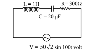
For a series LCR circuit, I vs ω curve is shown :
(a) To the left of ωr, the circuit is mainly capacitive.
(b) To the left of ωr, the circuit is mainly inductive.
(c) At ωr, impedance of the circuit is equal to the resistance of the circuit.
(d) At ωr, impedance of the circuit is 0.
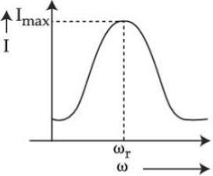
Choose the most appropriate answer from the options given below.
1
(a) and (d) only
2
(b) and (d) only
3
(a) and (c) only
4
(b) and (c) only
Official Solution
Correct Option: (3)
The correct option is(C): (a) and (c) only
We know that
and XL = ωL
Also, at ω = ωr : XL = XC
⇒ For ω<ωr : capacitive
and At
06
PYQ 2022
medium
physicsID: jee-main
The logic performed by the circuit shown in the figure is equivalent to:
1
AND gate
2
OR gate
3
NOR gate
4
NAND gate
Official Solution
Correct Option: (1)
According to the circuit,
Y = (A′ + B′)′
⇒ Y = AB
⇒ AND gate
07
PYQ 2022
medium
physicsID: jee-main
To increase the resonant frequency in series LCR circuit-
1
Source frequency should be increased
2
Another resistance should be added in series with the first resistance.
3
Another capacitor should be added in series with the first capacitor.
4
The source frequency should be decreased.
Official Solution
Correct Option: (3)
f= × To increase the resonating frequency product of L and C should decrease. By joining the capacitor in series, the capacitor will decrease
08
PYQ 2022
easy
physicsID: jee-main
A battery of 6V is connected to the circuit as shown below. The current I drawn from the battery is
Official Solution
Correct Option: (1)
09
PYQ 2022
medium
physicsID: jee-main
The current flowing through an ac circuit is given by . How long will the current take to reach the peak value starting from zero?
1
2
3
4
Official Solution
Correct Option: (4)
The current will take its peak value in time
=
Hence, the correct option is (D):
10
PYQ 2022
medium
physicsID: jee-main
In the given circuit, the value of current will be __________ mA. (When )
Official Solution
Correct Option: (1)
as Then, the value of current ∴
So, the answer is .
11
PYQ 2023
easy
physicsID: jee-main
An LCR series circuit of capacitance and resistance of is connected to an AC source of frequency For maximum value of amplitude of current in circuit, the value of inductance is ___ . (Take )
Official Solution
Correct Option: (1)
So, the answer is .
12
PYQ 2023
easy
physicsID: jee-main
A series LCR circuit is connected to an source of The circuit contains a resistance , an inductor of inductive reactance , and a capacitor of capacitive reactance The power factor of circuit is The value of is :
Official Solution
Correct Option: (1)
The correct answer is 8. cosϕ=ZR=R2+(XC−XL)2R cosϕ=(80)2+(60)280 cosϕ=10080⇒108
So, x=8
13
PYQ 2023
medium
physicsID: jee-main
Three concentric shells A, B and C having surface charge density σ, –σ and σ respectively. The radii of A and B are 2 cm and 3 cm respectively. Electric potential at surface A is VA and at C is VC. If VA = VC then find the radius of C in cm.
Official Solution
Correct Option: (1)
Step 1: Write the Potential at Point
The potential at point is the sum of potentials due to charges , , and :
Substitute the given charges:
Simplify each term:
Combine terms:
Step 2: Relate to and
Using the condition , expand and simplify:
Cancel :
Factorize:
Step 3: Solve for
Substitute and :
Final Answer:
The value of is:
14
PYQ 2023
medium
physicsID: jee-main
Figure shows a part of an electric circuit. The potentials at the points a, b and c are 30V, 12V and 2V respectively. the currents through the 20 resistors will be.
1
0.2 A
2
0.6 A
3
0.4 A
4
1.0 A
Official Solution
Correct Option: (3)
Let potential of the junction be volts using junction law .
Solving for :
15
PYQ 2023
medium
physicsID: jee-main
An oscillating LC circuit consists of a 75 mH inductor and a 1.2 uF capacitor. If the maximum charge to the capacitor is 2.7μC. The maximum current in the circuit will be _____mA.
Official Solution
Correct Option: (1)
Step 1: Use the energy conservation in LC circuits - Maximum energy in capacitor = Maximum energy in inductor:
Step 2: Solve for - Substituting values: Simplifying:
Final Answer: The maximum current in the circuit is 9 mA.
16
PYQ 2023
medium
physicsID: jee-main
Ratio of thermal energy released in two resistors R and 3R connected in parallel in an electric circuit is:
1
1 : 1
2
1 : 3
3
1 : 27
4
3 : 1
Official Solution
Correct Option: (4)
- The power dissipated in a resistor is:
- For : , and for : .
- The ratio of powers:
17
PYQ 2023
medium
physicsID: jee-main
Given below are two statements : Statement I : When the frequency of an a.c. source in a series LCR circuit increases, the current in the circuit first increases, attains a maximum value and then decreases. Statement II : In a series LCR circuit, the value of power factor at resonance is one. In the light of given statements, choose the most appropriate answer from the options given below:
1
Both Statement I and Statement II are true.
2
Both Statement I and Statement II are false.
3
Statement I is correct but Statement II is false.
4
Statement I is incorrect but Statement II is true.
Official Solution
Correct Option: (1)
Both statements are correct based on the behavior of a series LCR circuit at resonance.
Statement I: As the frequency of the AC source in a series LCR circuit increases, the current initially increases, reaches a maximum at resonance, and then decreases as the frequency continues to rise. This is due to the changing impedance in the circuit.
Statement II: At resonance, the power factor of a series LCR circuit is one because the impedance is at its minimum, and the current and voltage are in phase.
18
PYQ 2023
medium
physicsID: jee-main
In the given circuit, the current (I) through the battery will be
1
1.5A
2
2.5A
3
1A
4
2A
Official Solution
Correct Option: (1)
Understanding the Problem
In the given figure, the diodes and are forward biased and the diode is reversed biased. We need to find the current through the battery.
Solution
1. Diode Analysis:
The diodes and are forward biased, so they act as short circuits (negligible resistance). The diode is reverse biased, so it acts as an open circuit (infinite resistance).
2. Equivalent Circuit:
The circuit simplifies to two resistors in parallel: one resistor and one resistor. The reverse-biased branch is effectively removed from the circuit.
3. Equivalent Resistance ( ):
The equivalent resistance of parallel resistors is given by:
Substituting the values:
4. Current Through the Battery (I):
Using Ohm's law, , where :
Final Answer
The current through the battery is .
19
PYQ 2024
medium
physicsID: jee-main
A series LCR circuit is subjected to an AC signal of 200 V, 50 Hz. If the voltage across the inductor (L = 10 mH) is 31.4 V, then the current in this circuit is ________ :
1
68 A
2
63 A
3
10 A
4
10 mA
Official Solution
Correct Option: (3)
The voltage across the inductor is given by:
where: - is the current in the circuit, - is the inductive reactance given by:
Given: - , - , - Frequency .
Step 1: Calculate the Inductive Reactance
Step 2: Calculate the Current Using the formula :
Solving for :
Therefore, the current in the circuit is .
20
PYQ 2024
medium
physicsID: jee-main
An AC voltage is applied to a series LCR circuit which drives a current . The average power dissipated is:
1
2
3
4
Official Solution
Correct Option: (4)
To determine the average power dissipated in the circuit, we start by identifying the expressions for the AC voltage and current provided:
Voltage:
Current:
The average power dissipated in an AC circuit can be expressed as:
Where:
is the root mean square (RMS) voltage.
is the root mean square (RMS) current.
is the phase angle between the voltage and current.
Step 1: Calculate RMS Values
For a sinusoidal function, the RMS value can be calculated as times its maximum (peak) value:
Step 2: Determine the Phase Angle ()
The phase difference given is , hence .
Step 3: Calculate Cosine of Phase Angle
Step 4: Calculate Average Power
Substitute these values into the average power formula:
The simplification is as follows:
Conclusion:
The average power dissipated in the circuit is . Thus, the correct answer is:
21
PYQ 2024
easy
physicsID: jee-main
A LCR circuit is at resonance for a capacitor C, inductance L and resistance R. Now the value of resistance is halved keeping all other parameters same. The current amplitude at resonance will be now:
1
Zero
2
double
3
same
4
halved
Official Solution
Correct Option: (2)
To solve the problem, let's analyze the behavior of an LCR circuit at resonance.
Concept Explanation: At resonance, an LCR circuit has its inductive reactance equal to its capacitive reactance, and the circuit impedance is purely resistive. The impedance is given by the resistance alone, thus:
The current amplitude at resonance is given by:
where is the peak voltage applied across the circuit.
Problem Statement Analysis:
Initially, for a resistance , the current at resonance is:
Now, the resistance is halved to , while the inductance and capacitance remain the same. Hence, the new current amplitude is:
Conclusion: The current amplitude at resonance will be double the initial current amplitude when the resistance is halved, assuming all other parameters remain constant.
Therefore, the correct answer is double.
22
PYQ 2024
medium
physicsID: jee-main
Output of given circuit represents which logic gate :
1
NAND
2
NOR
3
AND
4
OR
Official Solution
Correct Option: (4)
The Correct Option is (D): OR
23
PYQ 2024
medium
physicsID: jee-main
Given below are two statements: Statement I: In an LCR series circuit, current is maximum at resonance. Statement II: Current in a purely resistive circuit can never be less than that in a series LCR circuit when connected to the same voltage source. In the light of the above statements, choose the correct from the options given below.
1
Statement I is true but Statement II is false
2
Statement I is false but Statement II is true
3
Both Statement I and Statement II are true
4
Both Statement I and Statement II are false
Official Solution
Correct Option: (3)
Statement-I: At resonance, , so:
Thus, the impedance is minimum, and therefore, is maximum at resonance.
Statement-II: In a purely resistive circuit.
Hence, in a purely resistive circuit, the current cannot be less than that in a series LCR circuit.
Thus, both Statement I and Statement II are true.
24
PYQ 2024
medium
physicsID: jee-main
For a given series LCR circuit, it is found that maximum current is drawn when value of variable capacitance is . If resistance of and inductor is being used in the given circuit. The frequency of AC source is ____ . (Given )
Official Solution
Correct Option: (1)
The problem describes a series LCR circuit where the current is maximum, which occurs at resonance. We are given the values of capacitance, resistance, and inductance, and we need to find the frequency of the AC source.
Concept Used:
In a series LCR circuit, the current is maximum when the circuit is in resonance. This occurs when the inductive reactance ( ) equals the capacitive reactance ( ).
The formulas for the reactances are:
where is the angular frequency of the AC source, is the inductance, and is the capacitance. At resonance, the angular frequency ( ) is given by:
The relationship between angular frequency ( ) and frequency ( ) is . Therefore, the resonant frequency ( ) is:
At this frequency, the impedance of the circuit is minimum ( ), and thus the current is maximum.
Step-by-Step Solution:
Step 1: List the given values and convert them to SI units.
Capacitance,
Inductance,
Resistance, (This value is not needed to calculate the resonant frequency).
Given approximation, .
Step 2: Use the formula for the resonant frequency.
The frequency of the AC source must be the resonant frequency for the current to be maximum.
To simplify the calculation, let's square both sides of the equation:
Step 3: Substitute the given values into the squared formula.
Using , , and :
Now, let's simplify the denominator:
So, the equation for becomes:
Step 4: Calculate the resonant frequency .
Taking the square root of both sides:
So, the frequency of the AC source is .
Step 5: Express the result in the required format.
The problem asks for the frequency in the form _____ .
The value to be filled in the blank is 10.
25
PYQ 2024
medium
physicsID: jee-main
An ac source is connected in given series LCR circuit. The rms potential difference across the capacitor of 20 μF is .............. V.
Official Solution
Correct Option: (1)
The inductive reactance is:
The capacitive reactance is:
The total impedance is:
Simplifying:
The rms current is:
The rms voltage across the capacitor is:
26
PYQ 2024
medium
physicsID: jee-main
In series LCR circuit, the capacitance is changed from C to 4C. To keep the resonance frequency unchanged, the new inductance should be :
1
reduced by
2
increased by 2L
3
reduced by
4
increased by 4L
Official Solution
Correct Option: (3)
To keep the resonance frequency unchanged, we know:
Given:
Substituting into the equation:
Thus, the inductance must be decreased by:
27
PYQ 2025
medium
physicsID: jee-main
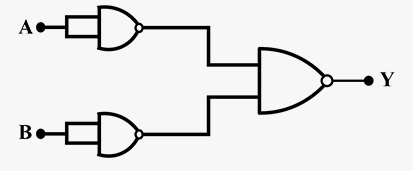
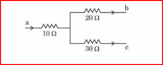
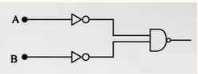
Find output voltage in the given circuit.
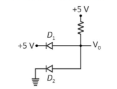
1
+5 Volt
2
0
3
10 Volt
4
-5 Volt
Official Solution
Correct Option: (2)
Step 1: Analyze the circuit. The circuit consists of two diodes ( and ) with a resistor connected in series with and arranged in a way where the output voltage is taken across the resistor. The input voltage is . Step 2: Understand the behavior of the diodes. is forward biased because its anode is at , and the cathode is at a higher potential relative to the ground. It conducts. , however, is reverse biased because its anode is at 0V (ground), and its cathode is connected to the potential. In reverse bias, will not conduct. Step 3: Analyze the voltage across the resistor.
Since is reverse biased and non-conducting, there will be no current flowing through the resistor. With no current, there is no voltage drop across the resistor. Step 4: Conclusion.
Since there is no current flowing through the resistor, the output voltage will be , because there is no voltage drop across the resistor.